
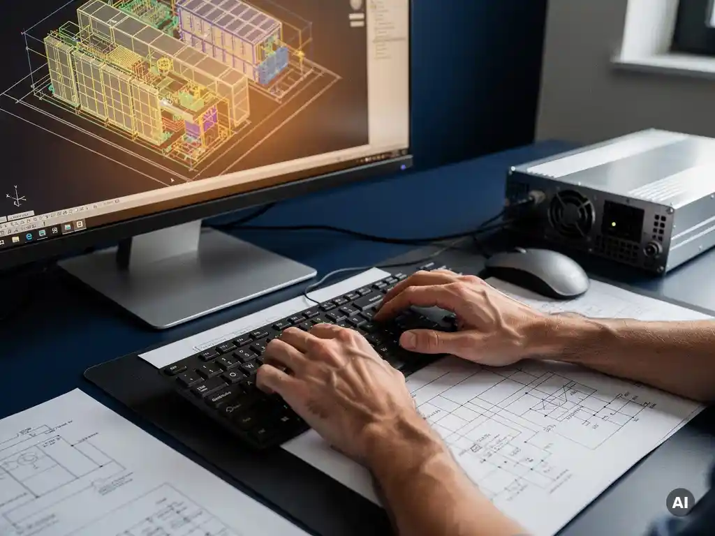

The tools that speed up battery storage system design include simulation software, integrated solar-plus-storage platforms, and automated CAD-based engineering tools. These solutions handle the most time-intensive tasks in BESS design: sizing, configuration, load flow analysis, and single-line diagram generation. The sections below break down each tool category and what to look for when choosing between them.
What types of software are used to design battery storage systems?
Battery storage system design typically relies on four categories of software: energy simulation tools, electrical engineering platforms, CAD-based design environments, and integrated solar-plus-storage applications. Each category addresses a different phase of the design workflow, from early-stage feasibility and sizing through to construction-ready documentation.
Energy simulation tools such as PVsyst, Homer Pro, and SAM (System Advisor Model) are widely used for modeling system performance, estimating round-trip efficiency losses, and evaluating how a battery storage system will behave across different load and generation scenarios. These tools are particularly valuable during the pre-engineering phase, where the goal is to validate whether a given battery capacity and chemistry makes economic and technical sense for the project.
Electrical engineering platforms handle the downstream calculations that follow a confirmed design: cable sizing, protection coordination, fault current analysis, and compliance with grid connection requirements. Tools in this category range from general-purpose power systems software to purpose-built BESS engineering environments.
CAD-based environments, including AutoCAD and BricsCAD with specialist plugins, are used to translate engineering decisions into construction-ready drawings. Single-line diagrams, DC and AC wiring layouts, and equipment placement drawings are all produced at this stage. For engineers already working inside CAD environments, this is where the bulk of manual effort has historically been concentrated.
Finally, integrated solar-plus-storage platforms combine layout, simulation, and documentation into a single workflow, reducing the need to transfer data between disconnected tools.
How does simulation software speed up BESS sizing and configuration?
Simulation software speeds up battery storage sizing and configuration by automating the iterative calculations that engineers would otherwise run manually through spreadsheets. Instead of testing each capacity scenario by hand, simulation tools model multiple configurations simultaneously, comparing performance metrics, degradation curves, and economic outcomes across different battery chemistries and inverter setups.
The core time saving comes from replacing the trial-and-error cycle. In a manual workflow, an engineer might size a battery system based on peak shaving targets, then recalculate when the load profile changes, then adjust again when the inverter selection shifts. Each change cascades through every downstream figure. Simulation software recalculates the entire model automatically when any input variable changes, which means engineers can test more scenarios in less time and arrive at an optimized configuration with greater confidence.
Simulation tools also accelerate the configuration of charge and discharge strategies. Rather than estimating how a battery will behave under a specific dispatch logic, engineers can model time-of-use optimization, frequency response, and backup power scenarios directly within the tool, then compare results side by side. This is particularly valuable for utility-scale and commercial battery storage projects where dispatch strategy has a significant impact on revenue and system sizing.
Another practical benefit is the ability to generate bankable performance reports directly from the simulation output. Lenders and offtakers increasingly require documented yield and performance data before committing to a project. Simulation software produces this documentation as a natural output of the sizing process, removing a separate reporting step from the workflow.
What’s the difference between standalone BESS tools and integrated solar-plus-storage platforms?
Standalone BESS tools are purpose-built for battery storage design in isolation, while integrated solar-plus-storage platforms handle PV generation and battery storage within a single connected workflow. The key difference is data continuity: integrated platforms carry solar generation data directly into battery sizing, eliminating the manual transfer step that introduces errors and delays in disconnected toolchains.
Standalone tools offer depth in specific areas. A dedicated BESS sizing tool may provide more granular control over battery chemistry parameters, degradation modeling, and grid services configuration than a general-purpose integrated platform. For projects where the battery system is the primary engineering focus, such as grid-scale standalone storage or behind-the-meter industrial applications, a specialist tool can be the right choice.
Integrated platforms, by contrast, are optimized for solar-plus-storage projects where the interaction between generation and storage is central to the design. When a PV array layout changes, the battery sizing updates automatically because both components live inside the same model. This tight coupling reduces rework significantly on projects where module selection, tilt angles, or shading conditions are still being refined while battery sizing is underway.
For engineering teams working on commercial and industrial solar-plus-storage projects, the practical advantage of an integrated platform is that it compresses what would otherwise be a multi-tool workflow into a single environment. The trade-off is that integrated platforms may not match the depth of a specialist BESS tool in every area. The right choice depends on whether the project is primarily a storage project with solar as a secondary input, or a solar project with storage as an integrated component.
Which tools handle single-line diagrams for battery storage systems?
Single-line diagrams for battery storage systems are typically produced in CAD environments, with AutoCAD and BricsCAD being the most widely used platforms in professional engineering practice. Specialist plugins extend these environments to automate SLD generation, reducing the manual drafting work that has traditionally made diagram production one of the most time-consuming steps in the electrical design process.
The challenge with battery storage SLDs is complexity. A BESS single-line diagram must represent the battery modules, battery management system, inverter or bidirectional converter, protection devices, metering, and grid connection point in a way that satisfies both engineering review and regulatory submission requirements. Drawing this manually for each project, and then redrawing it every time a component changes, consumes significant engineering hours.
Automated SLD tools address this by generating diagrams directly from the electrical design data rather than requiring engineers to draft each element by hand. When the inverter selection changes or a protection device is updated, the diagram updates accordingly. This is where tools like Virto.CAD add measurable value for engineers already working inside AutoCAD or BricsCAD: automatic SLD creation is built into the design workflow, so the diagram is a live output of the engineering model rather than a separate manual deliverable.
For teams that need SLDs but are not working in a CAD environment, some web-based integrated platforms include basic single-line diagram functionality. These are typically sufficient for early-stage documentation but may not meet the detail requirements for construction-ready or grid connection submissions.
What should engineers look for when choosing a BESS design tool?
When choosing a battery storage design tool, engineers should prioritize workflow integration, automation depth, and output quality. The most important question is whether the tool fits into the existing engineering environment or requires a parallel workflow that duplicates effort and introduces data transfer errors.
The following criteria are worth evaluating systematically:
- Integration with existing tools: Does the tool connect with the CAD environment, simulation software, or project management systems already in use? A tool that requires manual data re-entry between stages adds risk and time rather than removing it.
- Automation of repetitive calculations: Inverter sizing, string configuration, cable sizing, and protection coordination should be automated rather than requiring manual input for each project. The more of these tasks the tool handles automatically, the greater the time saving per project.
- SLD and documentation output: Construction-ready single-line diagrams and bills of materials should be generated directly from the design data, not produced as a separate manual step. Check whether the output format meets the requirements of local grid operators and permitting authorities.
- Scalability across project types: A tool that works well for a 500 kWh commercial BESS should also handle a 50 MWh utility-scale project without requiring a fundamentally different workflow. Scalability reduces the need to switch tools as project size increases.
- Update and revision handling: When component specifications change mid-project, the tool should propagate those changes through all downstream calculations and drawings automatically. Manual revision management is one of the highest-risk points in any engineering workflow.
- Vendor support and documentation: Engineering tools require ongoing support, particularly when regulatory requirements or equipment specifications change. Evaluate the quality of technical documentation and the responsiveness of the vendor’s support team before committing.
Beyond these criteria, the most reliable test is a structured trial on a real project. Benchmark the tool against the existing workflow on a project of representative complexity, and measure the actual time saving rather than relying on vendor estimates. If you want to explore how purpose-built solar engineering software fits into your BESS design process, speaking with our team is a practical starting point.
Frequently Asked Questions
How long does it typically take to design a BESS using automated tools compared to a manual workflow?
With automated BESS design tools, engineers commonly report reducing project design time by 40–70% compared to fully manual workflows. Tasks like string configuration, cable sizing, and SLD generation — which might take days in a spreadsheet-and-CAD workflow — can be completed in hours when automation handles the repetitive calculations. The actual time saving depends on project complexity, but the compounding effect across multiple projects makes the efficiency gain significant at the team level.
Can these tools handle hybrid projects that include solar, storage, and other generation sources like wind or diesel backup?
Some integrated platforms and simulation tools such as Homer Pro are specifically designed to model hybrid energy systems that combine solar, storage, wind, and diesel generation within a single model. However, not all BESS design tools support multi-source hybrid configurations — many are optimized for solar-plus-storage only. If your project includes additional generation sources, verify hybrid modeling capability before committing to a tool, and check whether the electrical design outputs (SLDs, cable schedules) reflect the full system architecture.
What are the most common mistakes engineers make when using BESS design software for the first time?
The most frequent mistake is treating the software output as a final deliverable without validating inputs against real project conditions — particularly load profiles, grid connection requirements, and local equipment availability. Engineers new to BESS tools also tend to underestimate the importance of degradation modeling, using default parameters rather than chemistry-specific data from the actual battery manufacturer. A third common issue is running the design tool in isolation from the CAD environment, which reintroduces the manual data transfer step the tool was meant to eliminate.
How do I know if a BESS design tool meets the documentation requirements for grid connection submissions in my region?
The most reliable approach is to request sample output files — particularly single-line diagrams and protection coordination reports — from the tool vendor and compare them directly against your local grid operator's submission checklist. Requirements vary significantly between jurisdictions: some grid operators accept PDF single-line diagrams, while others require specific CAD formats or standardized symbol libraries. It is also worth checking whether the tool has been used successfully on grid-connected projects in your region, as vendors with local reference projects can usually confirm compliance with regional standards.
Is it worth investing in a specialist BESS design tool for a team that only does a few storage projects per year?
For low-volume teams, the ROI calculation depends on project complexity rather than project count alone. A single utility-scale or complex commercial BESS project can justify the investment if the tool prevents even one significant revision cycle or accelerates a grid connection submission. For teams handling simpler behind-the-meter systems infrequently, an integrated solar-plus-storage platform with built-in storage functionality may offer a better cost-to-value ratio than a dedicated specialist tool, since it serves both the solar and storage design needs without requiring a separate software budget.
How should I approach migrating from a spreadsheet-based BESS design workflow to dedicated software?
The most practical approach is a parallel-run migration: select one upcoming project of moderate complexity and run it through both the new tool and your existing spreadsheet workflow simultaneously. This lets you validate the tool's outputs against calculations you already trust, identify any gaps in the tool's coverage, and build team familiarity without putting a live project at risk. Once the outputs align and the team is confident in the tool, transition fully on the next project rather than attempting a mid-project switch.
Can BESS design software integrate with energy management systems (EMS) or SCADA platforms used during project operation?
Design-phase BESS software and operational EMS or SCADA platforms serve different purposes and are generally not directly integrated, but the design outputs — particularly dispatch strategy configurations and system architecture data — should inform the EMS setup. Some advanced simulation tools allow engineers to export dispatch logic parameters that can be used as a starting point for EMS programming. When selecting a BESS design tool, it is worth confirming whether the vendor provides any structured handoff format or data export that simplifies the transition from design to operational configuration.
Related Articles
- How do you automate single line diagram creation in AutoCAD?
- What is BESS thermal management?
- What is the round-trip efficiency of a BESS?
- What makes a solar design construction-ready for utility-scale projects?
- What makes utility-scale projects different from rooftop solar?
This content was generated with the help of AI — it may contain mistakes