

How is row pitch calculated from tilt angle?
Row pitch is the module’s horizontal footprint plus the shadow-free gap behind it. Calculate it as pitch = L × cos(β) + L × sin(β) / tan(α), where L is the module length along the slope, β is the tilt angle, and α is the solar elevation angle at your design time.
Here is how the pieces fit together:
- Vertical height of the row: h = L × sin(β). This is how tall the back edge of the module stands above the front edge.
- Shadow length: d = h / tan(α). A lower sun means a longer shadow.
- Horizontal footprint of the tilted module: L × cos(β).
- Row pitch: the footprint plus the shadow length. The pitch is the front-to-front distance between rows, while the clear gap between rows is the pitch minus the footprint.
Most engineers define α using the winter solstice, often at 9:00 and 15:00 solar time, so rows stay unshaded during the core production hours. Some projects use a different design date or time window, which is a deliberate choice rather than a rule. If you also work with the ground coverage ratio (GCR), it is simply the module’s horizontal footprint divided by pitch, which makes it a handy way to express density.
Why does a steeper tilt require more row spacing?
A steeper tilt raises the back edge of each row, and a taller row casts a longer shadow when the sun is low. Longer shadows mean the next row has to sit farther back to stay clear, which increases the row pitch and reduces the number of rows on the site.
The relationship is geometric, not linear. At shallow tilts, adding a few degrees barely changes the shadow, because the module is still low to the ground. As the tilt climbs, the sine of the angle grows more slowly in absolute terms, so each extra degree adds less shadow length than the one before. On top of that, a lower sun angle at higher latitudes stretches every shadow further.
This is why the same module on the same roof needs very different spacing in Stockholm and in Madrid. Latitude sets the winter sun elevation, and the winter sun elevation sets how forgiving your tilt choice can be. It also explains why east-west layouts with low tilts can pack so densely: the shallow angles produce very short shadows.
What tilt angle gives the best energy yield versus density?
The best tilt for annual yield per module is usually close to the site’s latitude, but the best tilt for yield per area is often lower. Reducing the tilt lets you place more modules on the same land or roof, and the extra capacity frequently outweighs the small loss per module.
Think of it as two competing goals:
- Yield per module: favors a tilt near the optimal angle for your latitude, which captures the most irradiance across the year.
- Yield per area: favors a lower tilt with tighter pitch, because you can install more kWp in the same footprint.
- Project economics: depends on whether land, roof area, grid capacity, or budget is your binding constraint.
Annual energy near the optimum is fairly flat, so moving a few degrees below it usually costs little output while freeing meaningful space. That is why many commercial and utility designs settle on tilts well below the theoretical optimum. The right answer comes from simulating a few options, not from a single rule of thumb. Compare tilt and pitch combinations on total energy, specific yield, and cost per kWh, then pick the one that suits the site’s constraints.
How do flat roofs and ground-mount sites differ in spacing?
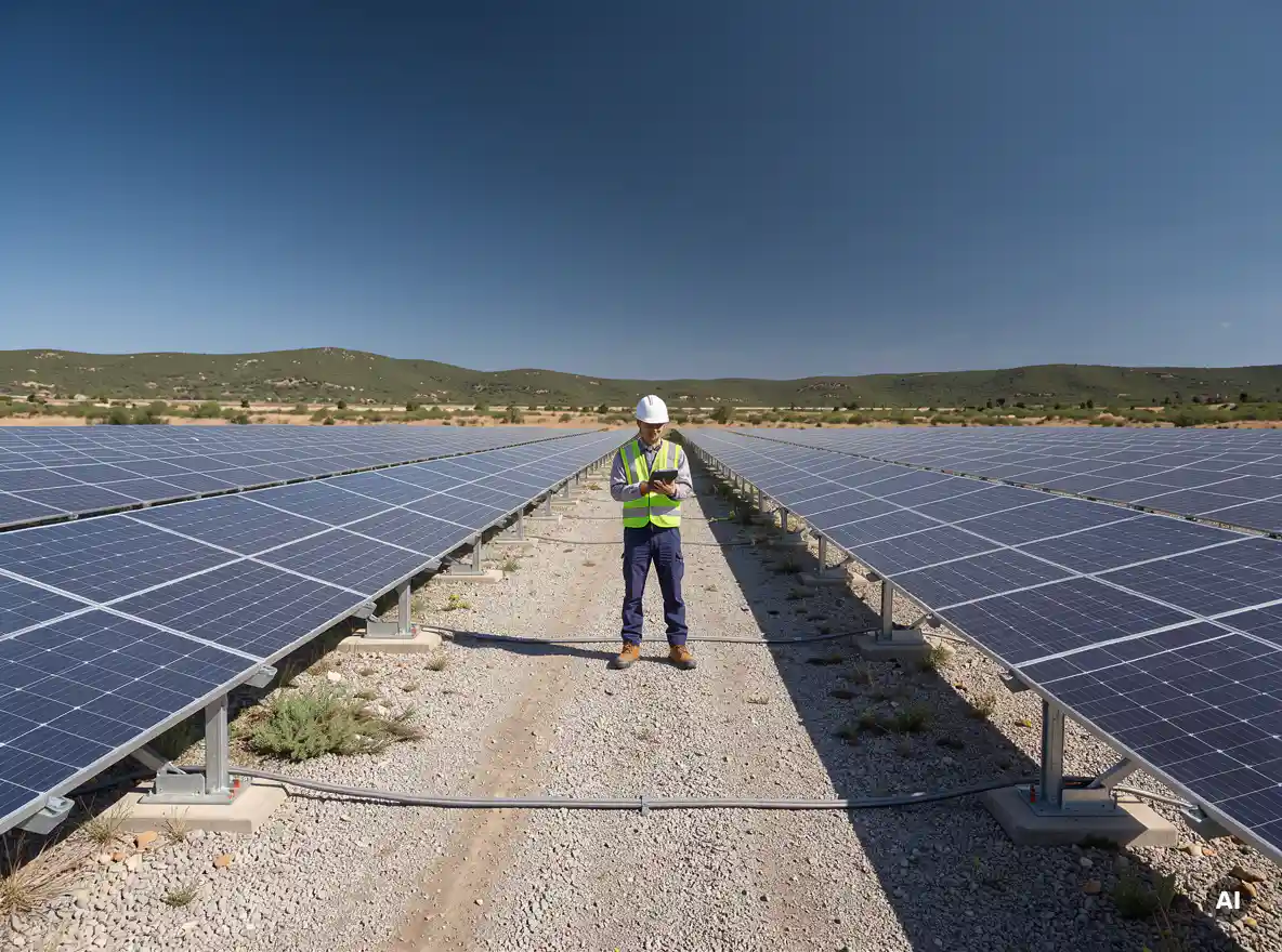
Flat roofs push designers toward low tilts and tight pitch because of limited area, wind loading, and ballast weight. Ground-mount sites allow steeper tilts and wider spacing because land is more flexible, though terrain slope and land cost still shape the final layout.
Flat roof layouts
On a flat roof, area is the scarce resource. Designers commonly choose low tilts, often with east-west arrangements, to keep shadows short and capacity high. Wind uplift and structural load limits also matter, since lower tilts reduce wind exposure and ballast requirements. Setbacks, walkways, skylights, and HVAC units further break up the usable area, so the layout becomes a puzzle of fitting rows around obstacles.
Ground-mount layouts
Ground-mount sites usually have more freedom, so the tilt can sit closer to the energy-optimal angle. Here, the spacing question often becomes a land-use question: more pitch means more land, more cabling, and longer access roads. Sloping terrain adds another layer, because a north-facing slope in the northern hemisphere effectively increases the needed pitch while a south-facing slope reduces it.
In both cases, the same formula applies. What changes is which constraint you optimize against.
How can you verify spacing and shading losses in a layout?
You verify spacing by running a shading analysis on the actual layout, checking row-to-row shadows across the year, and confirming the resulting shading loss in your yield simulation. A hand calculation gives a good starting pitch, but only a full analysis captures obstacles, terrain, and partial shading effects.
A practical verification workflow looks like this:
- Check the design-day shadows: confirm that rows are clear of each other at your chosen design times.
- Add real-world obstacles: include parapets, roof equipment, trees, and neighboring buildings.
- Model electrical shading effects: consider how partial shading affects strings and module orientation, since a small shadow can hit output harder than its area suggests.
- Run the yield simulation: compare the shading loss percentage between layout variants.
- Iterate on tilt and pitch: adjust and re-check until the trade-off between density and loss looks right.
The painful part is the iteration. Change the tilt and every downstream element, from string layout to cable lengths to drawings, needs rework. This is where we built Virto.CAD to help: it runs inside AutoCAD and BricsCAD, automates module placement, tilt calculations, and shading analysis, and updates the design when parameters change, so testing another tilt angle takes minutes instead of days.
If you are weighing tilt options on a complex site and want a second pair of eyes, get in touch with us and we will gladly talk through your layout.
Key takeaways
- Row pitch grows with tilt, because a taller row casts a longer shadow at low sun angles.
- Latitude and the chosen design time set how aggressive your spacing needs to be.
- The best tilt for yield per area is often lower than the best tilt per module.
- Flat roofs favor tight, low-tilt layouts; ground-mount sites allow more freedom but add terrain and land costs.
- Always verify the final layout with a shading analysis rather than relying on the formula alone.
Frequently Asked Questions
How do I get started choosing a tilt and row pitch for a new project?
Start by collecting your module dimensions, site latitude, and available area. Pick a design day (usually the winter solstice) and design hours such as 9:00 to 15:00 solar time, calculate the solar elevation, and use the pitch formula to get a baseline spacing. Then test two or three tilt options in a yield simulation and compare energy, specific yield, and cost per kWh before committing to one.
What if my site has very limited space but I still want high output?
Lower the tilt and tighten the pitch, or consider an east-west layout, which uses shallow angles and short shadows to pack more kWp into the same area. Check whether the extra capacity is limited by your inverter size or grid connection, since adding modules beyond that limit yields diminishing returns. A quick simulation of a lower-tilt variant versus the optimal-tilt variant will show the net gain.
Is it acceptable to design for a different date or time than the winter solstice?
Yes, as long as it is a deliberate and documented choice. Some projects accept minor winter shading in exchange for higher density, for example by designing around a narrower time window like 10:00 to 14:00. Use a yield simulation to confirm that the annual shading loss stays within an acceptable range, often a small single-digit percentage depending on project economics.
How does sloping terrain change my row spacing?
In the northern hemisphere, a north-facing slope increases the pitch you need because the shadow falls on rising ground, while a south-facing slope lets you tighten it. Instead of using one uniform pitch, calculate spacing row by row using the local slope, or use software that adjusts for terrain automatically. This avoids both over-spacing on favorable slopes and unexpected shading on unfavorable ones.
Does partial shading at the edge of a row matter if it only covers a small area?
It can matter more than the shaded area suggests. Shading a single cell row can trigger bypass diodes and cut the output of an entire module or string, depending on module orientation and wiring. Consider portrait versus landscape orientation, string layout, and module-level power electronics when evaluating borderline spacing, and check these effects in your shading analysis.
What are common mistakes when setting row pitch?
Frequent errors include confusing pitch with the clear gap between rows, using the wrong sun elevation for the latitude, ignoring terrain slope, and forgetting obstacles like parapets, walkways, and roof equipment. Another common mistake is calculating spacing once and not re-checking it after changing the tilt. Always re-run the shading check whenever tilt, module size, or layout boundaries change.
How can I make testing multiple tilt angles faster?
Use design software that links tilt, module placement, and shading analysis so changes propagate automatically. Tools like Virto.CAD, which runs inside AutoCAD and BricsCAD, update the layout when parameters change, so you can compare several tilt and pitch combinations without redrawing strings, cables, and drawings by hand. Whatever tool you use, keep a simple comparison table of energy, density, and shading loss for each variant.
Related Articles
- What tools help with battery sizing for EPC projects?
- What software is used for BESS design?
- Can PV design software reduce costly errors in construction drawings?
- Why are solar panel layouts different from what gets built?
- How do you validate solar system performance before construction?
This content was generated with the help of AI — it may contain mistakes