
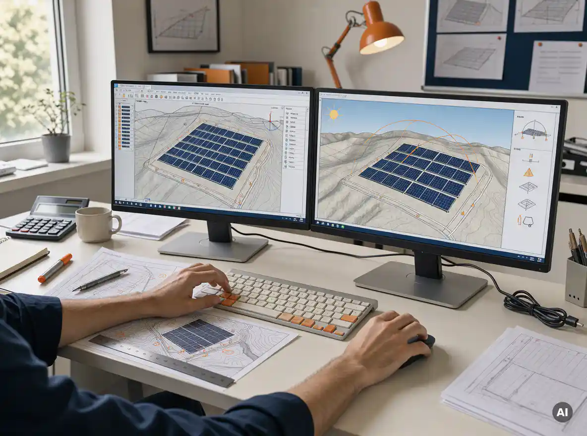

Yes, you can cut solar panel layout design time by up to 80 percent by automating repetitive tasks such as module placement, string planning, cable sizing, and bill of materials generation. The savings come from removing manual rework, not from rushing the engineering. We have seen this in practice, including a documented project in Belgium where design time dropped by 80 percent. Below, we answer the questions engineers ask most before changing their workflow.
Where does manual PV layout design time go?
Most manual solar panel layout design time disappears into repetition: placing modules row by row, recalculating strings, updating Excel sheets, and redrawing single-line diagrams after every change. The actual engineering decisions take a small share. The rest is data entry and rework.
Consider what happens when a module specification changes. Row spacing, string lengths, inverter loading, and cable sizes all shift. In a spreadsheet and CAD workflow, each downstream calculation has to be redone by hand, and every redo is a new chance for a typo to survive until commissioning.
The biggest time sinks usually include:
- Placing modules and tables manually around obstacles and boundaries
- Configuring strings and checking them against inverter limits
- Sizing DC and AC cables and routing trays
- Redrawing single-line diagrams after each revision
- Compiling the bill of materials from drawings
Which layout design tasks can be automated?
Any task that follows clear rules and repeats across projects can be automated. For PV layout design, that covers module placement, string configuration, inverter sizing checks, DC/AC ratio calculations, cable sizing, shading analysis, single-line diagram creation, and bill of materials generation.
Tasks that need judgment stay with you. Choosing a tilt strategy, deciding how to handle a tricky roof section, or weighing yield against cost are engineering calls. Automation simply gives you the time to test more options instead of finishing the first workable one.
A good rule of thumb: if you copy a number from one place to another, or redraw something that already exists in another form, a tool should be doing it for you.
Is an 80 percent time reduction realistic?
An 80 percent reduction is realistic for projects heavy on repetitive work, such as large rooftop and ground-mounted plants with many strings, tables, and revisions. In one documented project in Belgium, using Virto.CAD cut design time by 80 percent and saved several weeks of work.
Your own result will depend on a few factors:
- Project size: Larger plants have more repetition to automate, so the savings grow.
- Revision frequency: Projects that change often benefit most, because updates flow through automatically.
- Current workflow: Teams relying on spreadsheets and manual drawing have more to gain than teams already partly automated.
- Design complexity: Irregular roofs and heavy obstacles still need engineering attention.
So treat 80 percent as a strong benchmark, not a promise for every project. The only way to know your number is to measure it.
How can you measure design time savings accurately?
Measure savings by running one representative project through both workflows and comparing logged hours per task. Use the same scope, the same inputs, and the same quality checks. Counting only drawing time hides the real gains, so track calculation and revision time as well.
A simple approach works well:
- Pick a recent project you already completed manually and know well.
- Break the work into tasks: layout, stringing, cable sizing, SLD, BOM, and revisions.
- Log hours for each task in the manual workflow, using your project records.
- Redo the project with automation and log the same tasks.
- Simulate a late change, such as a different module, and time the rework in both cases.
That last step often shows the biggest difference. Manual rework scales with every change, while automated updates take minutes. Also compare error counts, since fewer late corrections are part of the real savings.
Can automation work inside AutoCAD or BricsCAD?
Yes, automation can run directly inside AutoCAD or BricsCAD through a plugin, so you keep the CAD environment you already know. Virto.CAD is built this way: it adds PV design automation on top of your existing drawing workflow instead of replacing it.
That matters for adoption. Your drawing standards, templates, and habits stay intact, and your team does not need to learn a new platform from scratch. You get construction-ready outputs, including DC/AC wiring layouts, cable tray routing, optimized module placement, and detailed bills of materials, without re-entering data between tools.
If your team also handles early-stage proposals, a web-based tool like Virto.MAX can generate quick layouts and yield simulations, so concept work and detailed engineering connect smoothly.
What should you check before switching workflows?
Before switching, check that the tool fits your CAD environment, supports your design scope, works with your existing standards, and proves its time savings on one of your own projects. A short pilot beats any feature list, because it shows real numbers.
Use this checklist:
- CAD compatibility: Does it run inside the software your team already uses?
- Project fit: Does it cover your typical systems, such as rooftop, ground-mount, or carport?
- Calculation transparency: Can you review and trust how results are produced?
- Interoperability: Does it work with your simulation tools and mounting system data?
- Onboarding effort: How quickly can your engineers become productive?
Start with one live project, keep your old method as a reference, and compare results. If you would like help setting up a pilot or want to talk through your workflow, get in touch with us and we will walk through it with you.
Frequently Asked Questions
How do I get started automating my PV layout workflow without disrupting current projects?
Start with a pilot on one completed or low-risk project rather than a live deadline-critical job. Pick a plugin that runs inside your existing CAD software, import your usual templates and standards, and automate one stage at a time, such as module placement and stringing first, then cable sizing and BOM. Keep your manual method as a reference so you can compare outputs and build trust in the results.
What if my project has irregular roofs or many obstacles? Will automation still help?
Yes, but expect to stay more hands-on. Automation handles the rule-based work like placing modules within boundaries, setting setbacks, and recalculating strings, while you make the judgment calls on tricky sections. Even on complex roofs, the time saved on recalculation, cable sizing, and BOM updates after each change is significant, though the total reduction may be below the 80 percent benchmark.
How do I make sure automated calculations are accurate and not a black box?
Validate the tool against a project you have already designed and signed off. Compare string lengths, inverter loading, DC/AC ratios, and cable sizes line by line, and check that the software lets you review the inputs and logic behind each result. Run this check again whenever you change standards or component libraries.
What are the most common mistakes teams make when adopting design automation?
The most common mistakes are trying to automate everything at once, skipping the pilot, and measuring only drawing time instead of calculation and revision time. Another is not updating templates and component libraries before starting, which leads to outputs that don't match company standards. Define your standards first, then let the tool enforce them.
How should I handle late design changes, like a different module or inverter, once automation is in place?
Change the component in your library or project settings and let the tool regenerate row spacing, strings, cable sizes, and the BOM. Then review the updated layout and single-line diagram for anything that needs engineering judgment, such as inverter loading limits or tray capacity. This is where automation typically saves the most time, since manual rework would mean redoing each calculation by hand.
Do I need a separate tool for early-stage proposals and detailed engineering?
Not necessarily, but it helps if the two connect. A web-based tool like Virto.MAX can produce quick layouts and yield simulations for concept and sales stages, while a CAD plugin like Virto.CAD handles construction-ready detail. Using connected tools avoids re-entering data when a proposal turns into a project.
How long does it take for engineers to become productive with a new automated workflow?
It depends on the tool, but plugins that work inside AutoCAD or BricsCAD usually have a shorter learning curve because engineers keep their familiar environment. Plan for a pilot project to double as training, with one or two engineers leading and sharing best practices with the team. Ask any vendor about onboarding resources and support before committing.
Related Articles
- How does battery storage support utility-scale solar projects?
- What is behind-the-meter battery storage?
- How do you size a battery for a solar system?
- How do you ensure solar designs will work for 25 years?
- What makes solar system design so complex?
This content was generated with the help of AI — it may contain mistakes