
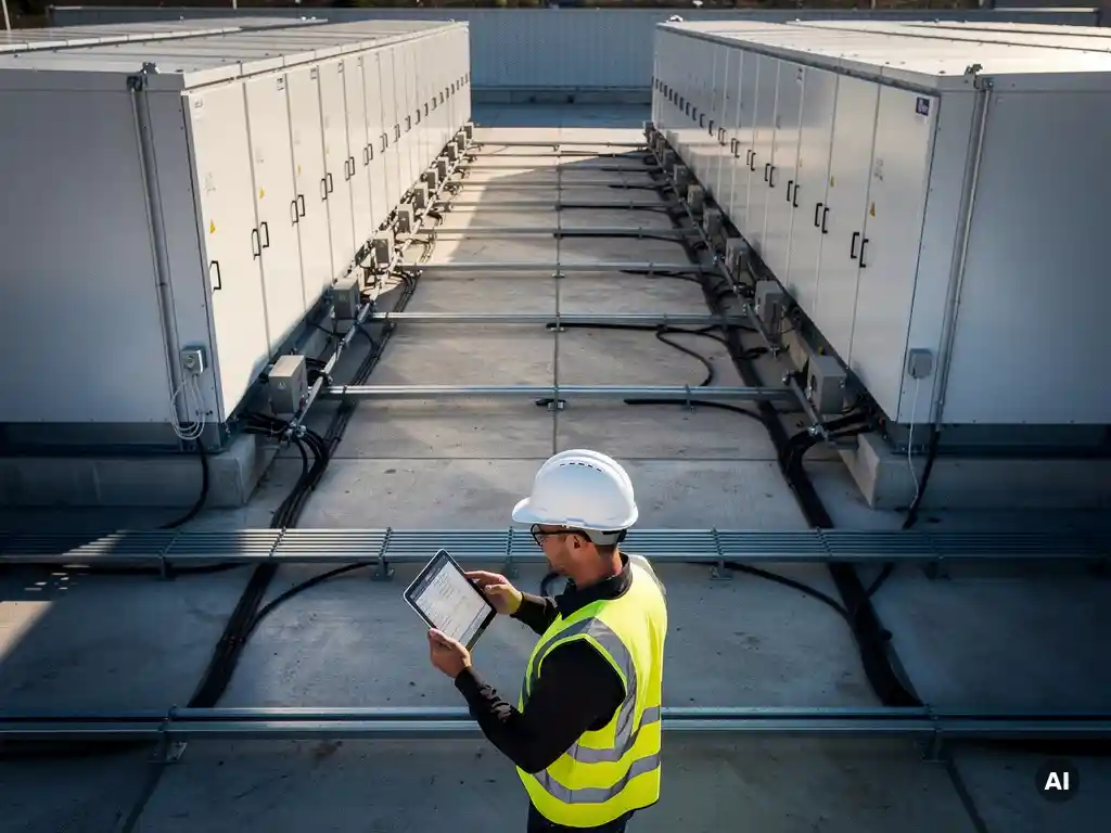

Designing a BESS for a utility-scale project means engineering a system that can store and dispatch large amounts of electrical energy reliably, safely, and economically. At its core, the process involves selecting the right battery chemistry, sizing the system to meet specific power and energy targets, choosing between AC-coupled and DC-coupled configurations, and integrating the storage system with the broader grid or solar plant. The sections below walk through each of the key design questions engineers face when approaching a utility-scale BESS project.
What components make up a utility-scale BESS?
A utility-scale BESS is made up of battery modules, a battery management system (BMS), power conversion equipment, thermal management systems, and a grid interconnection interface. These components work together to store electrical energy, manage cell-level performance, convert between DC and AC power, and protect the system from thermal and electrical faults.
Breaking this down further, the main building blocks are:
- Battery modules and racks: Individual lithium-ion (or alternative chemistry) cells are grouped into modules, which are then stacked into racks or containers. Most utility-scale deployments use containerized battery enclosures for easier transport and installation.
- Battery Management System (BMS): The BMS monitors cell voltage, temperature, and state of charge (SoC) at a granular level. It protects cells from overcharge, over-discharge, and thermal runaway, and communicates performance data to higher-level control systems.
- Power Conversion System (PCS): The PCS (also called a bidirectional inverter) converts DC power stored in the batteries to AC power for grid export, and AC to DC during charging. It controls charge and discharge rates and responds to grid frequency and voltage signals.
- Energy Management System (EMS): The EMS sits above the BMS and PCS, coordinating dispatch decisions based on grid signals, market prices, or solar generation forecasts. It is the intelligence layer of the system.
- Thermal management: Active cooling or heating systems maintain battery cells within their optimal operating temperature range, which directly affects performance, cycle life, and safety.
- Transformer and switchgear: Step-up transformers bring the system voltage to grid level, while switchgear and protection relays manage fault isolation and safe disconnection.
Understanding how these components interact is essential before sizing or configuring a BESS, because decisions made at the component level cascade into system-level performance and cost.
How do you size a BESS for a utility-scale project?
Sizing a utility-scale BESS starts with defining two key parameters: power capacity (measured in megawatts, MW) and energy capacity (measured in megawatt-hours, MWh). The ratio between these two values, known as the duration or C-rate, determines how long the system can discharge at full power. A 100 MW / 400 MWh system, for example, has a four-hour duration.
The sizing process is driven by the project’s intended use case. Common use cases and their sizing implications include:
- Frequency regulation: Requires high power output but short duration, typically 15 to 30 minutes. Systems are sized for fast response rather than large energy capacity.
- Peak shaving and load shifting: Requires longer durations, often two to four hours, to shift solar generation from midday into evening peak demand periods.
- Capacity firming: Requires sizing based on the variability of the paired renewable source and the grid operator’s firm-capacity requirements.
- Arbitrage: Sizing depends on the spread between low-price and high-price periods and the volume of energy that can be profitably cycled each day.
Beyond the use case, engineers must account for round-trip efficiency losses (typically 85 to 92% for lithium-ion systems), battery degradation over the project lifetime, and minimum state-of-charge limits that protect cell longevity. A system sized for 100 MWh of usable energy will need a nameplate capacity somewhat higher than 100 MWh to account for these factors over a 10 to 20-year project life.
Grid interconnection requirements and available land or footprint constraints also influence final sizing decisions, particularly for co-located solar-plus-storage projects.
What’s the difference between AC-coupled and DC-coupled BESS configurations?
In an AC-coupled BESS, the battery system connects to the AC bus of the plant through its own dedicated inverter, operating independently from the solar inverters. In a DC-coupled configuration, the battery shares a common DC bus with the solar array, connecting before the inverter stage. The key distinction is where in the electrical architecture the battery integrates.
AC-coupled configuration
AC coupling is the more common approach for retrofitting storage onto an existing solar plant, because the battery system can be added without modifying the existing PV inverters or DC wiring. Each component operates independently, which simplifies fault isolation and allows the BESS to charge from the grid as well as from solar generation. The trade-off is that energy passes through two conversion stages when charging from solar (DC to AC via the PV inverter, then AC to DC into the battery), which introduces additional efficiency losses.
DC-coupled configuration
DC coupling connects the battery directly to the solar array’s DC output, typically through a DC-DC converter or a shared string inverter. This eliminates one conversion stage when charging from solar, improving round-trip efficiency. DC coupling also allows the battery to capture clipped energy from an oversized solar array, which can meaningfully increase annual energy yield in projects with a high DC-to-AC ratio. The complexity is higher, and DC-coupled systems are generally better suited to greenfield projects where the entire electrical architecture is designed from the start.
The choice between AC and DC coupling depends on whether the project is a retrofit or greenfield, the importance of round-trip efficiency, the DC-to-AC ratio of the solar plant, and the grid operator’s interconnection requirements.
How does battery chemistry affect utility-scale BESS design?
Battery chemistry determines the energy density, cycle life, thermal behavior, and cost profile of a BESS, all of which directly shape system design decisions. Lithium iron phosphate (LFP) is the dominant chemistry for utility-scale storage in 2026, but other chemistries remain relevant for specific applications.
LFP offers a strong combination of thermal stability, long cycle life (often exceeding 4,000 to 6,000 cycles), and relatively low cost per kilowatt-hour. Its lower energy density compared to nickel manganese cobalt (NMC) chemistries means LFP systems require more physical space, but for ground-mounted utility projects where land is available, this is rarely a limiting factor. LFP’s thermal stability also reduces the risk of thermal runaway, which simplifies fire suppression design and reduces insurance costs.
NMC chemistry offers higher energy density, making it better suited to applications where footprint is constrained. However, NMC cells are more thermally sensitive and require more sophisticated thermal management and fire suppression systems, which adds cost and complexity.
Emerging chemistries such as sodium-ion and flow batteries are gaining attention for long-duration storage applications (eight hours or more), where lithium-ion’s cost per kilowatt-hour becomes less competitive. Flow batteries, in particular, decouple power and energy capacity, allowing engineers to size each dimension independently, which is advantageous for very long-duration use cases.
Chemistry selection feeds directly into thermal management system design, BMS configuration, container layout, and fire suppression strategy, so it must be resolved early in the engineering process.
What are the main electrical design considerations for a BESS?
The main electrical design considerations for a utility-scale BESS include system voltage architecture, protection coordination, grid interconnection requirements, and cable sizing for both DC and AC circuits. Each of these areas requires careful engineering to ensure safe, reliable, and code-compliant operation.
Key areas engineers must address include:
- System voltage and string configuration: Battery racks are connected in series and parallel combinations to achieve the required DC bus voltage for the PCS. Voltage levels must be compatible with the PCS input range and must comply with equipment ratings and safety standards.
- Protection coordination: Fuses, circuit breakers, and contactors must be selected and coordinated to isolate faults at the cell, module, rack, and system level without causing unnecessary outages. Arc-flash hazard analysis is required for utility-scale systems.
- Grid interconnection: Grid operators specify requirements for reactive power capability, frequency response, ramp rates, and anti-islanding protection. The PCS must be configured to meet these requirements, and the interconnection agreement will define the technical specifications the system must demonstrate during commissioning.
- Cable sizing: DC cables between battery racks and the PCS, and AC cables between the PCS and the point of interconnection, must be sized for continuous current, voltage drop limits, and short-circuit withstand ratings. Cable routing and tray design also affect installation cost and thermal performance.
- Grounding and bonding: Proper grounding of the battery enclosures, PCS, and transformer is critical for personnel safety and fault current management.
- SCADA and communications: Utility-scale BESS projects require robust SCADA integration to allow the grid operator or asset owner to monitor and dispatch the system in real time. Communication protocols such as Modbus, DNP3, or IEC 61850 are commonly specified.
Electrical design for a BESS is closely related to the electrical design of the solar plant it is paired with, and engineers who are already familiar with PV electrical design will find many of the same principles apply, though the bidirectional nature of storage introduces additional complexity.
How do you integrate a BESS with a utility-scale solar plant?
Integrating a BESS with a utility-scale solar plant requires aligning the electrical architecture, control systems, and grid interconnection strategy of both assets. The integration approach depends on whether the project is AC-coupled or DC-coupled, and whether the solar and storage systems share a single point of interconnection or connect to the grid separately.
For co-located solar-plus-storage projects, the most common integration model in 2026 uses a shared AC bus with a single point of interconnection. The solar inverters and the BESS PCS both connect to the same medium-voltage collector system, and a single step-up transformer connects the combined plant to the transmission or distribution grid. This approach simplifies the interconnection process and reduces infrastructure costs, but it requires the EMS to coordinate dispatch between the solar generation and the battery to stay within the interconnection capacity limit.
Control system integration is one of the most technically demanding aspects of the project. The EMS must receive real-time data from the solar inverters, the BMS, the PCS, and the grid meter, and use this data to make dispatch decisions that optimize revenue while respecting equipment limits and grid operator requirements. For projects participating in energy markets, the EMS must also interface with market scheduling systems and respond to dispatch instructions within defined response times.
From a design documentation perspective, integrating a BESS into a solar plant significantly increases the complexity of the single-line diagram, protection coordination study, and interconnection application. Engineers working on these projects benefit from tools that can handle the full scope of the electrical design without requiring manual rework every time a parameter changes. Our solar design software is built to support exactly this kind of complex, integrated PV engineering workflow, reducing the time spent on repetitive calculations and documentation so engineers can focus on the decisions that actually require their expertise.
If you are working on a utility-scale solar-plus-storage project and want to explore how purpose-built design tools can streamline your engineering workflow, get in touch with our team to discuss your project requirements.
Frequently Asked Questions
What is a realistic timeline for engineering and commissioning a utility-scale BESS project?
A utility-scale BESS project typically takes 18 to 36 months from initial design to commercial operation, depending on project size, grid interconnection queue timelines, and permitting complexity. The interconnection process alone can account for 12 to 24 months in congested markets, so initiating the interconnection application early is critical. Engineering, procurement, and construction (EPC) activities generally run in parallel with interconnection milestones to compress the overall schedule.
How does battery degradation affect long-term BESS performance, and how should engineers account for it in the design?
Lithium-ion batteries lose usable capacity over time due to calendar aging and cycle aging, with LFP systems typically retaining 70 to 80% of their original capacity after 10 years of regular cycling. Engineers account for this by oversizing the nameplate capacity at the start of the project so the system can still meet its contractual energy delivery obligations at end of life. Degradation modeling tools and manufacturer warranty curves are used to project capacity fade over the project lifetime and inform the required initial oversizing factor.
What are the most common mistakes engineers make when designing a utility-scale BESS for the first time?
One of the most frequent mistakes is undersizing the system by failing to account for round-trip efficiency losses, degradation, and minimum state-of-charge buffers, which results in a system that cannot meet its energy targets within a few years of operation. Another common error is treating the BESS as an isolated system rather than designing it as an integrated part of the broader plant electrical architecture, which leads to protection coordination gaps and SCADA integration challenges during commissioning. Starting with a clearly defined use case and working backward through the sizing and configuration decisions helps avoid both pitfalls.
What fire suppression and safety standards apply to utility-scale BESS installations?
Utility-scale BESS projects in the United States are primarily governed by NFPA 855 (Standard for the Installation of Stationary Energy Storage Systems), which sets requirements for system size limits, separation distances, fire suppression, and ventilation. NFPA 68 and NFPA 69 address deflagration and explosion prevention, which are relevant for enclosed battery enclosures. Internationally, IEC 62933 and local building codes apply, and many jurisdictions require a third-party hazard analysis and approval from the authority having jurisdiction (AHJ) before construction can begin. Chemistry selection significantly influences which suppression systems are required, with LFP generally allowing simpler suppression designs than NMC.
Can a utility-scale BESS operate as a standalone system without being paired with solar generation?
Yes, standalone BESS projects that charge exclusively from the grid are a well-established and growing segment of the market, particularly for frequency regulation, capacity, and arbitrage applications. These systems connect directly to the transmission or distribution grid through a PCS and transformer, without any co-located generation. The design process is similar to a solar-plus-storage project, but the EMS dispatch logic is driven entirely by grid signals and market prices rather than solar generation forecasts, and the interconnection requirements may differ depending on the grid operator's rules for standalone storage.
How do grid operators typically test and verify a BESS before it is allowed to participate in energy markets?
Most grid operators require a formal commissioning and acceptance testing process before a BESS can participate in energy markets or provide grid services. This typically includes functional testing of the PCS response to frequency and voltage signals, verification of ramp rates and response times, confirmation that the EMS can receive and execute dispatch instructions within required timeframes, and demonstration of anti-islanding protection. Some markets also require periodic re-testing to confirm the system continues to meet performance standards as it ages. Engineers should review the specific interconnection agreement and market participation rules early in the design process, as these requirements directly influence PCS configuration and EMS programming.
What revenue streams are available for utility-scale BESS projects, and how does the design need to support multiple use cases?
Utility-scale BESS projects can generate revenue through energy arbitrage, capacity market payments, ancillary services such as frequency regulation and spinning reserves, and transmission congestion relief, depending on the market structure where the project is located. Designing a system to participate in multiple revenue streams simultaneously, known as value stacking, requires an EMS sophisticated enough to optimize dispatch across competing opportunities in real time. From a hardware perspective, the system must be sized and configured to meet the technical requirements of each target market, which sometimes means accepting a higher upfront cost in exchange for greater revenue flexibility over the project lifetime.
Related Articles
- How do you avoid errors when drawing solar wiring diagrams manually?
- How do you size a battery for utility-scale storage?
- How do you calculate battery capacity for backup power?
- How do you size a battery for a commercial rooftop project?
- How do you design a battery storage system for an EPC project?
This content was generated with the help of AI — it may contain mistakes