
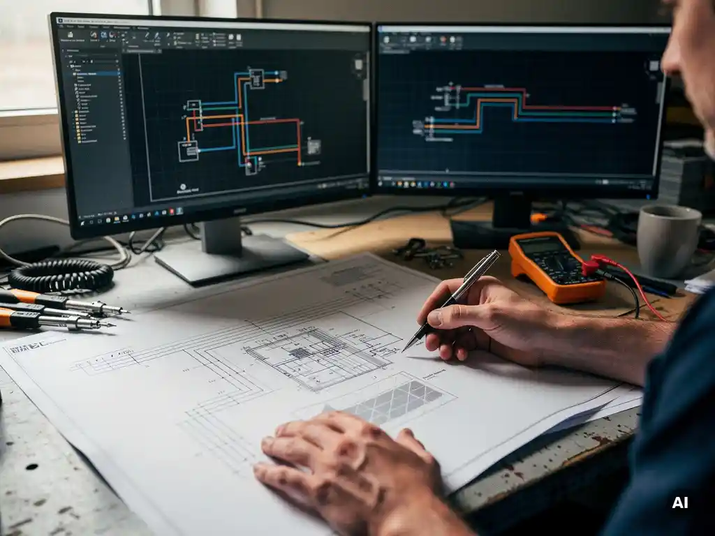

Battery storage integrates with existing wiring diagrams by adding new components between the solar array, inverter, and grid connection points. The specific wiring changes depend on whether the system uses AC coupling or DC coupling, and whether a hybrid inverter replaces the original grid-tie inverter. The sections below walk through every major question engineers face when updating a PV wiring diagram to include battery storage.
What components are added to a wiring diagram when battery storage is included?
When battery storage is added to a PV system, the wiring diagram must include the battery bank itself, a battery management system (BMS), a charge controller or hybrid inverter, dedicated overcurrent protection, and isolation switches for the battery circuit. Depending on the coupling method, additional AC or DC disconnect devices and metering points are also required.
Each of these components serves a distinct function and must appear on the diagram with correct ratings, wire sizing, and connection points. The battery bank is typically represented as a block with voltage and capacity labels. The BMS sits between the battery terminals and the rest of the circuit, monitoring cell voltage, temperature, and state of charge. Overcurrent protection devices, such as fuses or circuit breakers, are placed on both the positive and negative battery conductors. Isolation switches allow the battery to be safely disconnected during maintenance or fault conditions.
For utility-scale and commercial projects, the diagram also needs to show communication wiring between the BMS, inverter, and any energy management system. This control layer is separate from the power circuit but is essential for safe and efficient operation, and omitting it from the single-line diagram is a common documentation error.
What’s the difference between AC-coupled and DC-coupled battery wiring?
In a DC-coupled system, the battery connects on the DC side of the inverter, between the solar array and the inverter input. In an AC-coupled system, the battery has its own dedicated inverter and connects on the AC side of the main inverter. The key distinction is where in the power flow the battery sits, which changes the wiring diagram significantly.
DC-coupled wiring
In a DC-coupled configuration, a charge controller or hybrid inverter manages the flow of DC power from the array to both the battery and the inverter. The wiring diagram shows a single DC bus where the array, battery, and inverter input all meet. This layout is more efficient because energy only undergoes one DC-to-AC conversion, but it requires a hybrid inverter capable of managing both the PV input and the battery simultaneously.
AC-coupled wiring
In an AC-coupled configuration, the existing grid-tie inverter remains in place and a separate battery inverter is added on the AC side. The wiring diagram shows two inverters connected to the same AC bus, with the battery inverter handling charging and discharging independently. AC coupling is often chosen when retrofitting storage onto an existing solar installation because it avoids replacing the original inverter, though the diagram becomes more complex with additional protection and metering requirements at the AC connection point.
How does a hybrid inverter change the single-line diagram?
A hybrid inverter consolidates the functions of a grid-tie inverter, a battery charge controller, and sometimes a transfer switch into a single device. On the single-line diagram, this replaces what would otherwise be multiple separate components with one central unit, simplifying the DC side while adding new connections for the battery port and the backup AC output.
The SLD must now show the hybrid inverter with at least three distinct connection points: the PV array input, the battery terminal, and the AC grid connection. If the inverter includes a backup or off-grid output, a fourth connection appears, typically feeding a critical loads panel that is separated from the main distribution board by a transfer switch built into the inverter.
Engineers updating an existing SLD for a hybrid inverter retrofit need to remove the original string inverter symbol, add the hybrid inverter block with all its ports labeled, update the DC string wiring to reflect any new input configuration, and add the battery circuit with its protection devices. The AC side of the diagram also changes if the hybrid inverter handles anti-islanding differently from the original inverter, which may affect the utility interconnection point labeling.
Where does the battery connect in a grid-tied solar wiring diagram?
In a grid-tied solar wiring diagram, the battery connects either at the DC bus between the array and the inverter (DC coupling) or at the AC bus between the inverter and the main distribution panel (AC coupling). The exact connection point determines how the battery charges, discharges, and interacts with the grid.
For DC-coupled systems, the battery terminal appears on the diagram between the DC combiner output and the inverter DC input. A bidirectional DC-DC converter or the hybrid inverter itself manages current flow in both directions. The diagram must clearly show the polarity of the battery connection and the rating of the overcurrent protection on each conductor.
For AC-coupled systems, the battery inverter connects to the AC bus at a point between the main solar inverter output and the utility meter or main breaker. The diagram needs to show both inverters, their respective AC outputs, and how they share the AC bus without creating a backfeed conflict. A clearly labeled point of common coupling is essential for both safety review and utility interconnection approval.
What protection devices must appear in a battery storage wiring diagram?
A battery storage wiring diagram must include DC fuses or circuit breakers on the battery conductors, an isolation switch or disconnect for the battery circuit, surge protection devices on both the DC and AC sides, and a ground-fault protection device. For grid-tied systems, an anti-islanding protection mechanism must also be documented.
The BMS provides the first layer of protection at the cell level, but it does not replace external overcurrent devices. A dedicated fuse or breaker sized to the battery’s maximum continuous discharge current must appear on the positive conductor close to the battery terminals. Many standards also require a manual disconnect switch that is accessible without tools, so the battery can be isolated quickly during an emergency.
On the AC side, the battery inverter output requires its own overcurrent protection before it connects to the AC bus. If the system includes a backup output feeding a critical loads panel, that circuit needs its own breaker and a clear indication on the diagram that it is a non-utility source. Surge protection devices should be shown at both the DC battery terminal and the AC inverter output, particularly for systems in areas with high lightning exposure.
For commercial and utility-scale projects, the wiring diagram review process often requires explicit labeling of each protection device with its rated current, interrupt capacity, and voltage rating. Missing any of these labels is one of the most common reasons battery storage diagrams are returned for revision during permitting.
How do wiring diagrams change for off-grid versus grid-tied battery systems?
Off-grid battery system wiring diagrams do not include a utility interconnection point, anti-islanding protection, or a grid-side meter. Instead, they show a generator input, a larger battery bank, and a charge controller or off-grid inverter that manages all load supply independently. The overall diagram is self-contained, with no external reference point to the utility grid.
In a grid-tied battery diagram, the utility connection is a central reference point that defines voltage, frequency, and the direction of energy flow. Protection devices are designed to disconnect the system from the grid under fault conditions. The diagram must show the point of common coupling, the utility meter, and any required interconnection equipment such as a transfer switch or grid protection relay.
In an off-grid diagram, the inverter output becomes the reference voltage for the entire system. The diagram must show how loads are distributed across the AC output, how the generator connects and is prioritized relative to the battery, and how the charge controller manages the relationship between the PV array and the battery bank. Battery sizing and autonomy calculations are more prominent in off-grid documentation because there is no grid fallback.
Hybrid systems that can operate both on-grid and off-grid add the most complexity to a wiring diagram. These diagrams must show the transfer switch logic, the conditions under which the system islands intentionally, and how reconnection to the grid is managed safely. Engineers working on these designs benefit from software that automates single-line diagram generation as system configurations change. Tools like Virto Solar’s design platform are built to handle exactly this kind of complexity, reducing the risk of documentation errors when battery storage is added to an existing PV project. If you are working through a battery storage integration and want guidance on the right approach for your project, reaching out to our team is a good starting point.
Frequently Asked Questions
How do I know whether AC coupling or DC coupling is the right choice for my battery retrofit?
The best starting point is evaluating whether your existing grid-tie inverter is worth keeping. If it is relatively new and still under warranty, AC coupling lets you add storage without replacing it, which lowers upfront costs. If the inverter is aging or undersized for an expanded system, DC coupling with a hybrid inverter is often the more cost-effective long-term solution because it eliminates the efficiency losses of a double conversion and simplifies the overall wiring diagram.
What are the most common mistakes engineers make when updating a PV wiring diagram to include battery storage?
The most frequent errors are omitting the BMS communication wiring from the single-line diagram, failing to label protection devices with their full ratings (current, voltage, and interrupt capacity), and not clearly identifying the point of common coupling for AC-coupled systems. Another common oversight is leaving out the manual disconnect switch for the battery circuit, which is required by most standards and is a frequent reason diagrams are sent back during permitting review.
What wire sizing considerations are specific to battery circuits that don't apply to standard PV string wiring?
Battery circuits must be sized for continuous bidirectional current, meaning both the charge and discharge rates need to be accounted for — not just the peak PV output. Unlike PV string conductors, battery conductors can carry high surge currents during discharge, so the wire gauge and the overcurrent protection device must both be rated for the battery's maximum short-circuit current. Voltage drop calculations also need to account for round-trip losses, which become especially important in larger battery banks where conductor runs are longer.
Do I need a separate permit or utility approval specifically for the battery storage addition, even if the solar system is already approved?
In most jurisdictions, yes — adding battery storage to an already-permitted solar system requires a separate permit and, for grid-tied systems, an updated interconnection agreement with the utility. The utility needs to review the revised single-line diagram to confirm that anti-islanding protection, backfeed limits, and metering arrangements still comply with their interconnection standards. It is worth contacting your local authority having jurisdiction (AHJ) and utility early in the design process, as requirements vary significantly by region and can affect how the wiring diagram must be structured.
How should the wiring diagram document a battery system that is designed to operate in both grid-tied and off-grid (islanding) modes?
The diagram must explicitly show the transfer switch or internal inverter logic that governs the transition between grid-tied and islanded operation, including the conditions that trigger each mode. The intentional islanding zone — the loads and circuits that remain energized when the grid is disconnected — should be clearly delineated, typically by showing the critical loads panel as a separate branch fed from the backup output. Reconnection logic and any required anti-islanding delays should also be noted, either directly on the diagram or in an accompanying design specification, to satisfy both the AHJ and the utility during review.
Can I use the same wiring diagram software I currently use for PV-only systems, or do I need a specialized tool for battery storage designs?
Many general-purpose CAD tools can produce battery storage wiring diagrams, but they require manual updates every time a component or configuration changes, which increases the risk of documentation errors. Specialized solar design platforms that support battery storage — such as Virto Solar's design platform — automate single-line diagram generation as system parameters change, ensuring that protection device ratings, connection points, and component labels stay consistent throughout the design process. For complex hybrid or commercial-scale projects, a purpose-built tool significantly reduces revision cycles during permitting.
What labeling standards or codes should I reference to make sure my battery storage wiring diagram meets compliance requirements?
In the United States, the primary references are NEC Article 706 (Energy Storage Systems), Article 690 (Solar Photovoltaic Systems), and UL 9540 for the battery system as a whole. For utility interconnection, IEEE 1547 sets the standard for protection and anti-islanding requirements. Internationally, IEC 62619 covers safety requirements for battery systems and IEC 62109 addresses inverter safety — your AHJ will specify which standards apply in your jurisdiction, so confirming this before finalizing the diagram avoids costly revisions later.
Related Articles
- What is a solar wiring diagram?
- Why do utility-scale solar projects go over budget so often?
- How do you manage multiple solar projects simultaneously?
- What makes solar system design so complex?
- What makes solar project engineering so time-consuming?
This content was generated with the help of AI — it may contain mistakes