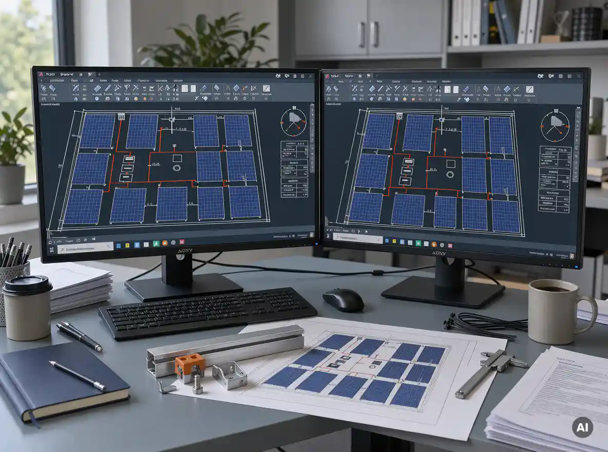
A construction-ready solar panel layout design is a complete, buildable package: exact module positions, string and wiring routes, inverter and combiner locations, mounting and structural details, site constraints, and the documents that tie them together, such as a single-line diagram and a bill of materials. It gives installers everything they need to build without guessing.
In practice, that means every number on the drawing has been checked against real equipment, real site conditions, and real code requirements. Below, we answer the key questions engineers ask when moving a solar panel layout design from concept to construction.
How does a buildable layout differ from a concept layout?
A concept layout shows roughly where modules could fit and what energy the site might produce. A buildable layout locks in every component, dimension, and connection so crews can install it as drawn. The difference is precision: concept drawings support decisions, while buildable drawings support construction.
Concept layouts are typically made during sales or tender stages. They use simplified assumptions, such as approximate row spacing, generic module data, and rough capacity targets. They answer the question “does this project make sense?”
A construction-ready layout answers a different question: “can we build this exactly as shown?” To get there, the design must include:
Final module, inverter, and mounting system selections with confirmed dimensions
Verified row spacing and tilt based on shading analysis
Defined string configurations that respect inverter voltage and current windows
Cable routes, sizes, and lengths calculated for the actual site
Coordinates and details that match surveyed site conditions
Think of the concept layout as the sketch and the buildable layout as the blueprint. Skipping the step between them is how errors slip through to commissioning.
What electrical details must a construction-ready layout show?
A construction-ready layout must show string configurations, inverter and combiner positions, DC and AC cable routes with sizes, grounding, protection devices, and a single-line diagram. Every electrical element needs to be traceable from module to grid connection, with calculations that confirm the design stays within equipment and code limits.
For engineers, the electrical scope typically covers:
String planning: Modules per string and strings per MPPT, checked against minimum and maximum voltage at temperature extremes
DC/AC ratio: The relationship between installed module capacity and inverter capacity, documented and justified
Cable sizing: Conductor cross sections based on current, length, and acceptable voltage drop
Cable routing: DC and AC paths, trays, trenches, and conduits shown on the plan
Protection and earthing: Fuses, breakers, surge protection, and grounding layouts
Single-line diagram (SLD): A schematic of the full electrical path from modules to the point of connection
The SLD and the physical layout must agree. If a string count changes on the plan but not in the diagram, someone will find out on site. This is one of the biggest reasons teams automate the connection between the two.
Which mechanical and site details are required in the drawings?
Mechanical and site drawings must show the mounting structure type, module orientation and tilt, row spacing, foundation or ballast details, access paths, setbacks, and obstacles. Together they tell the construction crew where every post, rail, and module goes and what physical constraints they must work around.
The key items to include are:
Mounting system layout: Structure type, rail or frame positions, and attachment or foundation points
Module placement: Orientation, tilt angle, and exact positions within each array
Spacing and shading clearances: Row pitch and distances from obstacles such as parapets, HVAC units, trees, or fences
Site boundaries and setbacks: Property lines, fire access paths, and any restricted zones
Terrain or roof data: Slope, elevation changes, roof load limits, or ground conditions
Equipment pads and enclosures: Inverter stations, transformers, and monitoring cabinets
For rooftop projects, structural limits and penetration points matter most. For ground-mounted plants, terrain, drainage, and pile layout take center stage. In both cases, the drawing should leave nothing for the installer to interpret.
What documents come with a construction-ready layout package?
A construction-ready package includes the layout drawings, single-line diagram, cable schedules, a bill of materials, and supporting calculations such as string sizing, voltage drop, and shading analysis. Many teams also attach energy yield simulations and equipment datasheets so reviewers can verify every assumption.
A typical package contains:
Layout drawings: Plan views with module, string, and equipment positions
Single-line diagram: The electrical schematic of the full system
Bill of materials (BOM): Quantities of modules, mounting components, cables, and electrical hardware
Cable and string schedules: Lengths, sizes, and string assignments in table form
Calculation reports: String sizing, voltage drop, DC/AC ratio, and shading results
Yield simulation: Often prepared in or compatible with tools like PVsyst
Equipment datasheets: Module, inverter, and mounting system specifications
The BOM deserves special attention. Procurement orders it, installers use it to count what arrives on site, and any mismatch with the drawings becomes a delay or a cost overrun. Generating it directly from the design, instead of counting by hand, removes a common source of error.
How do you keep a layout accurate when designs change?
To keep a layout accurate when designs change, link drawings, calculations, and outputs to a single source of design data so updates flow through automatically. Manually editing each drawing and spreadsheet separately invites inconsistencies, especially when module specs, row spacing, or inverter choices change late in the project.
Design changes are normal. A client switches modules, a landowner shifts a boundary, or a grid operator updates requirements. The risk lies in how the change spreads:
A new module with different dimensions changes row pitch, string lengths, cable quantities, and the BOM
A new inverter model changes string limits and the SLD
A boundary shift changes module count, DC capacity, and yield
If these updates live in separate Excel files and CAD drawings, each one must be redone by hand. That is slow, and it is where mistakes hide until commissioning.
A better approach is to design inside your CAD environment with automation that regenerates strings, cables, the SLD, and the BOM when inputs change. That is exactly what we built
Virto.CAD to do as a plugin for AutoCAD and BricsCAD. Engineers keep working in the tools they already trust, while repetitive calculations and documentation update automatically. In one documented project in Belgium, this approach cut design time by 80%, saving several weeks of work.
Whatever tools you use, a few habits help: freeze equipment selections early, document assumptions, review the layout against the SLD after every revision, and check the BOM before release.
Want to see how automation could fit your solar panel layout design workflow?
Get in touch with us and we will gladly walk you through it.
Frequently Asked Questions
Where should I start if I'm moving from concept layouts to construction-ready designs for the first time?
Start by building a standard checklist from the package outlined above: confirmed equipment datasheets, survey data, layout drawings, SLD, cable schedules, BOM, and calculation reports. Pilot it on a single small project, then note where manual steps or mismatches occurred. Those pain points show you where templates, standard details, or automation will pay off first.
What site data should I collect before starting a buildable layout?
At minimum, gather a topographic or roof survey, property boundaries and setbacks, geotechnical or structural reports, obstacle locations (parapets, HVAC units, trees), and grid connection requirements. For ground-mounts, add drainage and soil data; for rooftops, add roof load capacity and penetration restrictions. Missing or outdated survey data is one of the most common reasons layouts need rework during construction.
How do I verify that my string design is safe across temperature extremes?
Calculate the maximum open-circuit voltage at the site's lowest expected temperature and confirm it stays below the inverter's maximum DC input voltage. Then calculate the string's maximum power point voltage at the highest expected cell temperature and confirm it stays above the inverter's minimum MPPT voltage. Use the module's temperature coefficients from the datasheet and local climate data, and document the results in your calculation report.
What are the most common mistakes that cause a layout to fail on site?
The usual culprits are a mismatch between the SLD and the plan, outdated module dimensions after a late equipment swap, cable lengths estimated rather than measured from the actual routes, and a BOM that wasn't updated after revisions. Other frequent issues include ignoring access paths and setbacks, and underestimating voltage drop on long DC runs. A final cross-check of drawings, schedules, and BOM before release catches most of these.
What if the client changes the module or inverter after the layout is already approved?
Treat it as a formal revision: re-check row pitch and shading, string lengths and voltage windows, cable sizes and quantities, the SLD, and the BOM. If your drawings and calculations are linked to a single source of design data, many of these updates can be regenerated automatically rather than redone by hand. Also record the change and its impact on cost and yield so the client can approve it knowingly.
How should I choose a DC/AC ratio for a project?
Base it on the site's irradiance profile, inverter limits, grid export limits, and project economics, then document the justification. A higher ratio can improve inverter utilization and lower cost per kWh but increases clipping losses at peak production. Run yield simulations, for example in PVsyst, at a few different ratios to compare energy output against the added module cost.
Can I automate parts of the layout design without leaving my existing CAD software?
Yes. Plugins that work inside AutoCAD or BricsCAD can automate module placement, string and cable generation, SLD creation, and BOM output while you continue working in a familiar environment. When evaluating tools, look for features that keep drawings, calculations, and outputs synchronized after every design change, since that is where manual workflows lose the most time and accuracy.
Related Articles
This content was generated with the help of AI — it may contain mistakes