
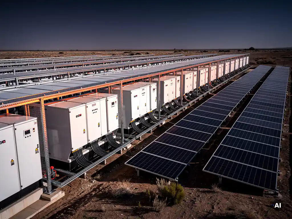

A Battery Energy Storage System (BESS) is integrated into a solar PV system by connecting battery storage to the PV array, inverter, and grid through either an AC-coupled or DC-coupled architecture. The integration allows excess solar energy to be stored and discharged on demand rather than exported or wasted. The sections below walk through every key question engineers face when designing a solar-plus-storage system.
What components connect a BESS to a solar PV system?
The core components connecting a BESS to a solar PV system are the battery modules, a battery management system (BMS), an inverter or bidirectional converter, protection devices, and the communication and control infrastructure that ties them together. Each component plays a distinct role in ensuring safe, efficient energy flow between the PV array, the battery bank, and the load or grid.
The battery modules store DC energy in electrochemical cells, most commonly lithium iron phosphate (LFP) or nickel manganese cobalt (NMC) chemistry at the utility and commercial scale. The BMS monitors cell voltage, temperature, and state of charge (SoC), protecting the battery from overcharge, deep discharge, and thermal events. Without a functioning BMS, even a well-sized battery bank becomes a liability.
The inverter or bidirectional converter is the electrical bridge between the DC battery and the AC grid or load. Depending on the system architecture, this may be a hybrid inverter, a dedicated battery inverter, or a DC-DC converter paired with a separate string inverter. Protection devices, including fuses, DC disconnects, surge protection devices (SPDs), and contactors, are mandatory at every interface point to meet electrical codes and grid operator requirements.
Finally, communication infrastructure such as CAN bus, Modbus, or EtherNet/IP connects the BMS to the inverter and energy management system (EMS), enabling coordinated dispatch, state-of-charge monitoring, and remote diagnostics. Without this layer, the system cannot respond intelligently to grid signals or self-consumption targets.
What is the difference between AC-coupled and DC-coupled BESS?
In a DC-coupled BESS, the battery connects directly to the DC bus between the PV array and the inverter, so solar energy charges the battery without an additional AC conversion step. In an AC-coupled BESS, the battery connects on the AC side through its own dedicated inverter, meaning energy is converted from DC to AC and then back to DC when charging. The key difference is conversion efficiency and design flexibility.
DC-coupled architecture
DC coupling is typically more efficient because it avoids the double conversion loss inherent in AC coupling. A hybrid inverter or a DC-DC charge controller manages the power flow directly from the PV array to the battery. This architecture is well suited to new-build projects where the entire system is designed from scratch, since the inverter, array, and battery sizing must all be coordinated from the outset. DC-coupled systems also allow the battery to be charged even when the grid is unavailable, which is a significant advantage for off-grid and backup-critical applications.
AC-coupled architecture
AC coupling is more flexible for retrofitting storage onto an existing solar installation because the original PV inverter remains in place. A separate bidirectional battery inverter is added on the AC bus. The trade-off is a modest efficiency penalty from the additional conversion stage. AC-coupled systems are also easier to scale independently since the battery inverter capacity is not constrained by the original PV inverter rating. For large commercial and utility-scale projects where the PV system is already operational, AC coupling is often the more practical and cost-effective path.
How does a hybrid inverter manage solar and battery power?
A hybrid inverter manages solar and battery power by continuously monitoring PV generation, load demand, battery state of charge, and grid conditions, then routing power according to a predefined dispatch strategy. It acts as the central intelligence of the system, deciding in real time whether to charge the battery, supply the load, export to the grid, or draw from storage.
During peak solar hours, the hybrid inverter prioritizes self-consumption: it supplies the local load first, then directs surplus generation to charge the battery. Once the battery reaches its upper SoC limit, excess power is exported to the grid if the connection agreement permits. When solar generation drops below load demand, the inverter seamlessly draws from the battery to cover the shortfall before importing from the grid.
Modern hybrid inverters also respond to time-of-use (ToU) tariff signals, charging the battery during low-tariff periods and discharging during peak-price windows to maximize economic return. Grid-forming-capable hybrid inverters can additionally provide frequency and voltage support, which is increasingly required by grid operators as penetration of variable renewables grows. The dispatch logic is typically configurable through the inverter’s EMS interface, allowing engineers to tailor the operating mode to the project’s specific revenue stream or resilience requirement.
What sizing calculations are needed to integrate a BESS with solar?
Integrating a BESS with a solar PV system requires calculating usable battery capacity, inverter power rating, charge and discharge rates (C-rate), DC/AC ratio adjustments, and round-trip efficiency losses. These calculations must be aligned with the project’s energy objectives, whether that is self-consumption maximization, peak shaving, backup duration, or grid services.
The starting point is the energy balance: how much excess solar generation is available for storage, and how much energy is needed during discharge periods. This requires hourly or sub-hourly load profile data and a yield simulation of the PV array. From this, the required usable capacity in kilowatt-hours is derived. Usable capacity is always less than nameplate capacity because the battery operates within a defined SoC window, typically between 10% and 90%, to protect cell longevity.
The inverter power rating must accommodate both the PV array output and the battery charge or discharge rate simultaneously in a DC-coupled system. The C-rate, which expresses charge or discharge current relative to battery capacity, determines how quickly the battery can be filled or emptied. A 1C rate means the battery charges or discharges fully in one hour. Most commercial LFP systems operate at 0.5C to 1C for optimal cycle life.
Engineers also need to account for round-trip efficiency, typically 85% to 95% for modern lithium systems, when calculating how much energy is actually recovered from storage. Oversizing the battery to compensate for conversion losses is a common design error that inflates cost without improving performance. Accurate sizing requires iterating between the energy model, the inverter specification, and the battery datasheet, which is exactly the kind of repetitive, calculation-heavy workflow where purpose-built solar design software delivers measurable time savings.
What are the grid connection requirements for a solar-plus-storage system?
Grid connection requirements for a solar-plus-storage system typically include compliance with the relevant grid code, anti-islanding protection, export limitation settings, metering configuration, and, in many markets, a formal grid impact study or application to the distribution network operator (DNO). Requirements vary by country, voltage level, and system size.
At the protection level, the inverter must meet the grid code’s requirements for voltage and frequency ride-through, reactive power capability, and anti-islanding detection. Standards such as IEEE 1547 in North America, VDE-AR-N 4105 in Germany, and G99 in the UK set the technical baseline. Adding a BESS to an existing PV connection often triggers a reassessment of the connection agreement because the system’s export profile changes, particularly if the battery can discharge independently of solar generation.
Export limitation is a common grid operator requirement for solar-plus-storage systems. The EMS or inverter must be configured to cap total export at the agreed connection capacity, even when both the PV array and battery are simultaneously capable of exporting. This requires a revenue-grade meter at the point of common coupling (PCC) and a control loop between the meter and the inverter that responds within seconds to prevent export exceedance.
Metering configuration also becomes more complex with storage. Many grid operators require separate metering for import, export, and battery charge or discharge to ensure accurate settlement and avoid double-counting of renewable generation. Engineers should confirm metering requirements with the DNO early in the design process to avoid costly retrofits at commissioning.
How does adding a BESS change the solar PV design workflow?
Adding a BESS to a solar PV project expands the design workflow to include battery sizing, inverter selection or reconfiguration, updated single-line diagrams, additional protection coordination, revised grid connection documentation, and a more complex energy yield model. Each of these steps adds engineering hours if managed manually, but the design sequence itself follows a logical extension of the standard PV workflow.
The most immediate change is to the single-line diagram (SLD). The SLD must now show the battery bank, BMS, bidirectional inverter or hybrid inverter, DC and AC disconnects, metering points, and the communication architecture. In a DC-coupled system, the DC bus topology becomes significantly more complex, with multiple source inputs requiring careful protection coordination to prevent backfeed faults.
The energy model must be updated to simulate battery dispatch alongside PV generation. Tools like PVsyst support basic battery modeling, but detailed dispatch optimization often requires supplementary simulation. The yield model output directly informs the financial model, so errors at this stage propagate into the project’s revenue projections.
Cable sizing and conduit routing also change. The battery room or container introduces new DC cable runs, often at high current and low voltage, which require careful voltage-drop and short-circuit current calculations. Thermal management of the battery enclosure adds another engineering discipline to coordinate.
For engineering teams handling multiple solar-plus-storage projects simultaneously, the accumulated design burden is substantial. Automating the repetitive calculation and drawing tasks, from string planning and cable sizing to SLD generation, is where tools like Virto.CAD make a direct impact on delivery speed and design accuracy. If you want to see how that fits your current workflow, get in touch with our team to discuss your project requirements.
Frequently Asked Questions
Can an existing solar PV system be retrofitted with a BESS without replacing the original inverter?
Yes, in most cases an existing solar PV system can be retrofitted with a BESS using an AC-coupled architecture, which allows the original PV inverter to remain in place. A separate bidirectional battery inverter is added on the AC bus, avoiding the need to replace or reconfigure the existing string inverter. However, you should verify that the original inverter's grid connection agreement still applies after storage is added, as the DNO may require a reassessment of the export profile and protection settings before commissioning.
What is the best battery chemistry for a commercial solar-plus-storage project?
Lithium iron phosphate (LFP) is currently the dominant choice for commercial and utility-scale solar-plus-storage projects due to its superior cycle life (typically 4,000–6,000 cycles), inherent thermal stability, and competitive cost per kilowatt-hour. NMC chemistry offers higher energy density, which can be advantageous where space is constrained, but it carries a higher thermal risk profile that demands more rigorous BMS and fire suppression design. For most commercial projects where longevity and safety take priority over energy density, LFP is the practical default.
How do I determine the right C-rate for my BESS application?
The right C-rate depends on your dispatch strategy and the battery chemistry you select. For self-consumption and daily cycling applications, a 0.5C rate is typically sufficient and extends cycle life by reducing stress on the cells. If your project targets peak shaving with short, high-power discharge windows or grid frequency response services, a 1C or higher rate may be required — but this should be explicitly confirmed against the battery manufacturer's datasheet, as exceeding the rated C-rate accelerates degradation and can void the warranty.
What happens to the BESS if the grid goes down — will it automatically provide backup power?
Not automatically in all system configurations — it depends on whether the inverter is grid-forming capable and whether the system has been designed with an islanding or backup mode. In a standard grid-tied system, anti-islanding protection will disconnect the inverter when the grid fails, cutting off both solar and battery output for safety reasons. To enable backup power during outages, the system must include a transfer switch, a grid-forming inverter capable of operating in island mode, and a dedicated backup load panel — all of which need to be specified and wired at the design stage, not added as an afterthought.
How does battery degradation affect long-term energy yield projections?
Battery degradation reduces usable capacity over time, which directly impacts the energy available for discharge and, consequently, the project's long-term revenue or savings projections. Most LFP batteries are warranted to retain 70–80% of their nameplate capacity after 10 years or a specified number of cycles, whichever comes first. Engineers should incorporate an annual degradation factor — typically 2–3% per year for LFP — into the energy model to produce realistic yield forecasts and avoid overstating financial returns in later project years.
What are the most common design mistakes when integrating a BESS with a solar PV system?
The most common mistakes include undersizing the inverter power rating so it cannot handle simultaneous PV generation and battery charging, oversizing the battery capacity to compensate for round-trip efficiency losses rather than accounting for them accurately in the energy model, and neglecting to confirm metering and export limitation requirements with the DNO before finalizing the design. Another frequent error is failing to coordinate DC protection devices correctly in DC-coupled systems, which can result in backfeed faults that damage equipment or fail inspection. Catching these issues early through a structured design review — ideally supported by purpose-built solar design software — is far less costly than correcting them during commissioning.
Do I need a separate energy management system (EMS), or can the hybrid inverter handle dispatch on its own?
For smaller commercial systems with straightforward dispatch goals — such as self-consumption maximization or basic time-of-use shifting — the built-in EMS logic of a modern hybrid inverter is often sufficient. However, for larger or more complex projects involving multiple inverters, grid services contracts, demand response programs, or multi-site optimization, a dedicated EMS provides the granular control, data logging, and remote management capabilities that inverter-embedded logic cannot match. The decision should be driven by the project's revenue streams and operational complexity, not by the inverter vendor's default recommendation.
Related Articles
- How do you draw a wiring diagram for a commercial solar project?
- What is modular battery storage?
- What is the difference between energy-based and power-based battery sizing?
- What is the round-trip efficiency of a BESS?
- How do you calculate depth of discharge for battery sizing?
This content was generated with the help of AI — it may contain mistakes