
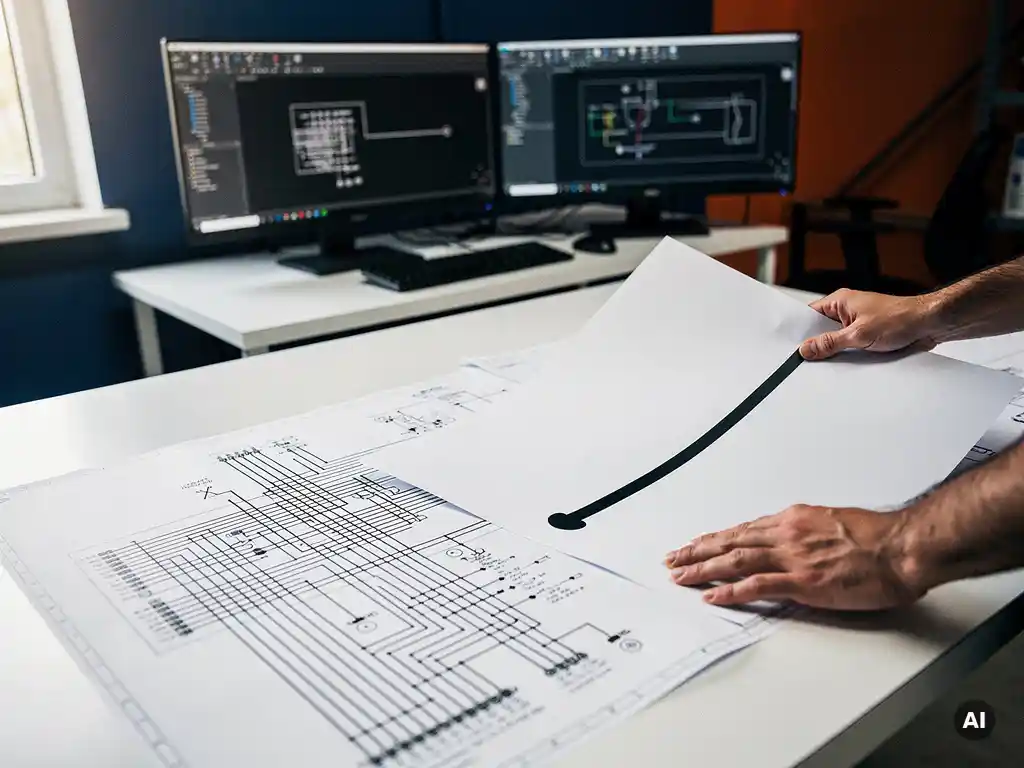

A single line diagram (SLD) uses one line to represent all three phases of an electrical system, giving a simplified overview of the system’s components and connections. A three-line diagram shows each phase as a separate conductor, revealing the full wiring detail of every phase, neutral, and ground connection. The key difference comes down to purpose: SLDs communicate system architecture quickly, while three-line diagrams are used when phase-by-phase accuracy is critical for protection, commissioning, or fault analysis. This article unpacks both diagram types, when each is required, and how they apply to solar PV projects.
What does a single line diagram actually show?
A single line diagram shows the overall electrical architecture of a power system using one line to represent all three phases, making it easier to read and communicate the layout of major components. It includes equipment such as inverters, transformers, switchgear, circuit breakers, meters, and busbars, along with their interconnections and ratings, without showing the individual conductors for each phase.
In solar PV projects, the SLD is one of the most important documents in the engineering package. It communicates how DC power flows from the PV array through combiner boxes, string inverters, or central inverters, AC disconnects, and into the grid connection point. For engineers, developers, and permitting authorities, the SLD provides a fast, clear snapshot of the system without getting buried in conductor-level detail.
Key elements typically shown on a solar SLD include:
- PV array configuration (number of strings, modules per string)
- Inverter type, quantity, and rated output
- Overcurrent protection devices and their ratings
- AC and DC disconnect switches
- Metering and monitoring equipment
- Transformer specifications (for utility-scale projects)
- Grid connection point and utility interface
Because the SLD condenses complex three-phase wiring into a single-line representation, it is the preferred format for permit applications, utility interconnection submissions, and client presentations. It is readable by a wide audience, from project managers to inspectors, without requiring deep electrical engineering expertise to interpret.
What does a three-line diagram show that an SLD doesn’t?
A three-line diagram shows each of the three phases as a separate conductor, revealing the complete wiring detail of every phase connection, neutral, and ground path. Unlike a single line diagram, it exposes how each phase is individually connected to every piece of equipment, making it possible to verify phase balance, protection coordination, and correct wiring at a granular level.
Where an SLD tells you that a transformer connects to a switchboard, a three-line diagram shows exactly how Phase A, Phase B, and Phase C are wired through that transformer, which terminals they land on, and how the neutral and ground conductors are routed. This level of detail is essential for commissioning engineers who need to verify that the physical installation matches the design intent before energizing the system.
Three-line diagrams also make it far easier to identify potential issues such as:
- Phase imbalance in the AC wiring
- Incorrect protection relay connections
- Neutral conductor routing errors
- Ground fault detection circuit wiring
- Current transformer (CT) polarity and placement
For solar projects with complex protection schemes, such as utility-scale plants with dedicated protection relays, differential protection, or anti-islanding systems, the three-line diagram is the document that commissioning and protection engineers work from directly. It is not a simplified overview; it is a precise wiring reference.
When is a three-line diagram required instead of a single line diagram?
A three-line diagram is required when phase-level detail is necessary for safety, protection coordination, or regulatory compliance. This typically applies to medium-voltage systems, utility-scale solar plants, projects with complex protection relays, and any installation where commissioning engineers need to verify individual phase connections before energizing the system.
For most commercial and industrial rooftop solar projects, an SLD is sufficient for permitting and construction. However, as project scale and system complexity increase, the limitations of a single-line representation become apparent. Utility interconnection agreements for large-scale plants often explicitly require three-line diagrams as part of the protection and control documentation package.
Situations where a three-line diagram is typically required include:
- Utility-scale PV plants connecting at medium or high voltage
- Projects with dedicated protection relays (overcurrent, differential, distance)
- Installations requiring detailed commissioning test documentation
- Systems with complex grounding schemes or neutral configurations
- Projects subject to grid code requirements that mandate phase-level documentation
- Fault analysis and post-incident investigation work
In practice, many large EPC firms produce both documents: the SLD for permitting and client communication, and the three-line diagram for the engineering and commissioning team. The two diagrams serve different audiences and different stages of the project lifecycle.
What are the main differences between a three-line diagram and a single line diagram?
The main difference between a three-line diagram and a single line diagram is the level of electrical detail shown. An SLD uses one line to represent all three phases and focuses on system architecture, while a three-line diagram draws each phase separately and captures the full conductor-level wiring of the system. This distinction affects who uses each diagram and at what stage of a project.
Here is a direct comparison of the two diagram types:
- Representation: An SLD uses a single line for all phases; a three-line diagram draws Phase A, B, and C as separate conductors
- Level of detail: An SLD shows component types and ratings; a three-line diagram shows individual phase connections, neutrals, and grounds
- Primary audience: SLDs are used by project managers, permitting authorities, and clients; three-line diagrams are used by protection engineers and commissioning teams
- Complexity: SLDs are faster to produce and easier to read; three-line diagrams are more time-intensive but more precise
- Typical use case: SLDs are standard for permit applications and utility submissions; three-line diagrams are required for protection relay settings and commissioning verification
- Project scale: SLDs are used across all project sizes; three-line diagrams are most common on medium-voltage and utility-scale installations
Neither diagram is inherently superior. They are complementary tools that serve different engineering needs. For most solar professionals working on commercial and industrial projects, the SLD is the primary solar wiring diagram they will produce and submit. The three-line diagram becomes relevant as project complexity and voltage levels increase.
How are single line diagrams created for solar PV projects?
Single line diagrams for solar PV projects are created by documenting the system’s electrical components and their connections in a standardized schematic format, typically using CAD software or dedicated PV design tools. The process involves defining the array configuration, selecting equipment, sizing protection devices, and then representing all of this in a clear, readable diagram that meets permitting and utility requirements.
Traditionally, engineers drew SLDs manually in AutoCAD, placing symbols for each component and drawing connection lines by hand. Every time a design changed, such as when a module specification was updated or an inverter was swapped, the SLD had to be redrawn from scratch. For large projects with multiple inverters, combiner boxes, and AC collection systems, this manual process could take days and introduced a significant risk of errors between the SLD and the underlying calculations.
Modern PV design software has changed this workflow significantly. Tools like Virto.CAD automate SLD generation directly from the project design, pulling component data, string configurations, and protection device ratings into a construction-ready diagram without manual redrawing. When the design changes, the SLD updates automatically, keeping the documentation consistent with the engineering calculations throughout the project lifecycle.
A well-produced solar SLD for a PV project should include:
- DC side: string configuration, combiner boxes, DC disconnect, and fusing
- Inverter specifications and quantity
- AC side: AC disconnect, overcurrent protection, and metering
- Transformer details (for medium-voltage projects)
- Grid connection point and utility meter
- Equipment ratings, wire sizes, and conduit specifications
- Relevant standards and code references
For engineering teams handling multiple projects simultaneously, the ability to generate accurate SLDs automatically is one of the most impactful efficiency gains available. If you want to see how automated SLD creation fits into a full PV design workflow, get in touch with our team to explore what is possible for your projects.
Frequently Asked Questions
Can I use a single line diagram for a utility-scale solar project, or do I always need a three-line diagram?
For utility-scale projects, you will almost always need both. The SLD is typically required for permit applications, utility interconnection submissions, and client communication, while the three-line diagram is required by the engineering and commissioning team for protection relay verification and phase-level wiring checks. Most utility interconnection agreements for large-scale plants explicitly list the three-line diagram as a mandatory deliverable in the protection and control documentation package, so planning for both from the start of the project will save time later.
What are the most common mistakes engineers make when producing a solar SLD?
The most frequent mistakes include omitting equipment ratings (such as breaker ampacity or fuse sizes), failing to update the SLD after design changes, and leaving out key components like AC disconnects, revenue meters, or grounding electrodes. Another common issue is inconsistency between the SLD and the supporting calculations — for example, showing a different wire size on the diagram than what appears in the voltage drop or short-circuit analysis. Using software that auto-generates the SLD from the design model significantly reduces these discrepancies.
How do I know which standards or codes my solar SLD needs to reference?
The applicable standards depend on your project location, voltage level, and the authority having jurisdiction (AHJ). In the United States, solar SLDs for commercial and residential projects typically reference NEC Article 690 (Solar Photovoltaic Systems), while utility-scale projects may also need to comply with IEEE 1547 for interconnection. In other regions, IEC 62446 sets out the documentation requirements for grid-connected PV systems. Always confirm requirements directly with the AHJ and the utility before finalizing the SLD, as local amendments can add or modify what must be shown.
What is the difference between a solar SLD and a wiring diagram, and do I need both?
A solar SLD shows the system architecture at a high level — components, ratings, and their relationships — without depicting every individual conductor. A wiring diagram (sometimes called a schematic or installation diagram) shows the physical routing of individual wires, terminals, and connections at the equipment level. For most commercial solar permit packages, the SLD is the primary required document. Wiring diagrams are more commonly needed for specific equipment connections, such as inverter AC and DC terminal wiring or combiner box layouts, and are often provided by equipment manufacturers rather than the design engineer.
How long does it typically take to produce a solar SLD, and how can I speed up the process?
Manually drafting an SLD in AutoCAD for a commercial rooftop project can take anywhere from a few hours to a full day, depending on system complexity and the engineer's familiarity with the design. For larger projects with multiple inverters and AC collection systems, manual SLD production can stretch to several days. The most effective way to reduce this time is to use PV design software that auto-generates the SLD directly from the project model, eliminating manual redrawing and keeping the diagram synchronized with design changes throughout the project lifecycle.
If the design changes after the SLD has been submitted for permitting, do I need to resubmit?
In most cases, yes — if the change affects equipment ratings, component types, or system configuration, the updated SLD will need to be resubmitted to the AHJ and potentially to the utility. Minor changes that fall within the original design parameters may be handled through a revision notice rather than a full resubmission, but this varies by jurisdiction. It is best practice to confirm the resubmission threshold with your AHJ early in the project, and to use a design workflow that makes SLD updates fast and accurate so that resubmissions do not become a bottleneck.
Do residential solar projects require a three-line diagram, or is an SLD always sufficient?
For the vast majority of residential solar installations, an SLD is all that is required for permitting and utility interconnection. Residential systems are typically single-phase or simple three-phase low-voltage installations without dedicated protection relays, making the phase-level detail of a three-line diagram unnecessary. The exception would be an unusually complex residential installation with advanced protection schemes or a utility that specifically requests phase-level documentation, which is rare at the residential scale.
Related Articles
- How do you design a battery storage system for an EPC project?
- What are the benefits of battery storage for commercial buildings?
- What is containerized battery storage?
- What causes rework in solar project engineering?
- Why do solar projects take so long to complete?
This content was generated with the help of AI — it may contain mistakes