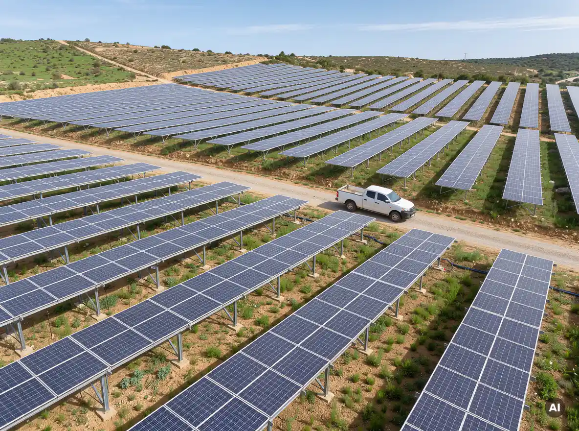
Solar panel layout design affects total energy yield by controlling shading losses, electrical mismatch, inverter loading, and cable losses. A well-planned layout can recover several percentage points of annual production without adding a single module, while a careless one quietly leaks energy for 25 years. The sections below cover the main levers: row spacing, tilt, stringing, and DC/AC ratio.
How much energy is lost to row-to-row shading?
Row-to-row shading typically costs a few percent of annual energy in a well-designed fixed-tilt system, but the loss can climb much higher when rows sit too close together. The exact figure depends on latitude, tilt, row pitch, and terrain. Treat any single number as a rough guide and calculate it for your actual site.
The tricky part is that shading losses are not proportional to the shaded area. Modern modules use bypass diodes and cell strings, so shading even a thin strip along the bottom edge of a portrait-oriented module can switch off an entire substring. That means a small shadow can trigger a disproportionately large electrical loss.
Shading also hits hardest in the low-sun hours of early morning and late afternoon, and in winter at higher latitudes. Because those hours contribute less energy than midday, many engineers accept a small amount of shading there in exchange for tighter packing. The key is to quantify the trade-off rather than guess.
What is the ideal row spacing for maximum yield?
There is no single ideal row spacing. The best spacing is the one that balances shading losses against land use and cost, and it depends on latitude, tilt angle, module height, and terrain slope. Wider rows reduce shading but increase cable runs, land requirements, and capital cost per kWp.
Most designers start from a design-day shading rule, such as keeping rows free of shadow from the row in front during a defined window around solar noon on the winter solstice. That gives a sensible starting pitch, but it is only a starting point. Final spacing should be tested against full-year shading simulations.
Several factors push the optimum in different directions:
Latitude: higher latitudes mean a lower winter sun and longer shadows, so rows need more space.
Tilt angle: steeper tilts raise the module’s upper edge and lengthen shadows.
Terrain: north-facing slopes (in the northern hemisphere) need more spacing than south-facing ones.
Land cost and availability: where land is expensive, tighter pitch with a higher shading loss may still win economically.
Bifacial gain: wider spacing lets more light reach the rear side, which can offset part of the extra land cost.
On flat commercial rooftops, the same logic applies with an added constraint: usable area is fixed, so engineers often choose between more modules at a lower tilt or fewer modules at a better tilt.
Do tilt and orientation matter more than layout?
Tilt and orientation set the baseline irradiance your modules receive, while layout determines how much of that potential you keep. Neither matters more in isolation. A perfect tilt with heavy shading underperforms, and a perfect layout at a poor orientation does too. They are coupled decisions that should be optimized together.
For fixed-tilt systems, the annual yield curve around the optimal tilt is fairly flat, so small deviations cost little. That flatness is useful: it lets you lower the tilt to shorten shadows and tighten row spacing, often gaining more from additional capacity than you lose from the slightly less ideal angle.
East-west layouts illustrate the coupling well. They give up some peak production compared with south-facing arrays, but they allow very dense packing with almost no row-to-row shading, flatten the daily production curve, and suit rooftops with limited area. Whether that wins depends on your site, your inverter loading, and your tariff structure.
How do string layout and stringing choices affect yield?
String layout affects yield through electrical mismatch, MPPT utilization, and cable losses. Modules in the same string carry the same current, so the weakest module limits the rest. Grouping modules that receive similar irradiance into the same string keeps mismatch losses low and helps each MPPT input work efficiently.
Good stringing follows a few practical principles:
Match irradiance within a string. Avoid mixing shaded and unshaded modules, or different orientations, in one string.
Respect inverter limits. Keep string voltage inside the MPPT window across the full temperature range, including cold-morning open-circuit voltage.
Balance string lengths. Equal strings per MPPT input simplify design and avoid unused capacity.
Shorten cable runs. Shorter DC cables mean lower resistive losses and lower material cost.
Portrait versus landscape module orientation also matters. In rows that shade each other, the choice changes which substrings are hit first and therefore how much power drops. Planning strings manually in spreadsheets makes it hard to test these variations, and every module change forces a recalculation of everything downstream. This is one of the areas where we built
Virto.CAD to help, automating string planning directly inside AutoCAD and BricsCAD so a layout change updates the electrical design with it.
How does layout influence DC/AC ratio and clipping losses?
Layout determines how much DC capacity you can fit and how it is distributed across inverters, which sets the DC/AC ratio. A higher ratio increases clipping losses at peak irradiance but improves inverter utilization the rest of the year. The goal is the ratio where extra modules still earn more than the energy they clip.
Clipping happens when DC production exceeds the inverter’s AC rating, and the surplus is lost. Orientation and tilt shape how often that occurs. A south-facing array peaks sharply at midday and clips more, while an east-west array spreads production across the day and tolerates a higher ratio with less clipping.
Layout choices that influence this balance include:
Splitting the array into east- and west-facing sections to flatten the production curve.
Distributing modules evenly across inverters and MPPT inputs so no unit saturates before the others.
Choosing a tilt that trades peak output for a broader production window.
The best DC/AC ratio is ultimately an economic question. Compare the cost of added modules against the marginal energy they deliver after clipping, and check the result against your site’s irradiance profile and any export limits.
How can engineers compare layout options faster?
Engineers can compare layout options faster by automating the repetitive parts of design: module placement, string configuration, shading analysis, and cable sizing. When those steps update together, testing five layouts takes about the same effort as testing one by hand. This turns layout optimization from a one-off task into a routine part of the process.
The usual bottleneck is rework. In a spreadsheet and CAD workflow, changing the row pitch or module type means redoing string counts, cable lengths, the bill of materials, and the single-line diagram. Because that effort is so costly, many teams settle on the first workable layout rather than the best one.
A practical comparison workflow looks like this:
Define two or three candidate layouts, varying row pitch, tilt, or orientation.
Run shading analysis for each across the full year.
Generate string plans and check inverter loading and DC/AC ratio.
Export results to your yield simulation tool, such as PVsyst, and compare net energy against cost.
This is where automation pays off. In one documented project in Belgium, using Virto.CAD reduced design time by 80%, saving several weeks of work. That freed time is what allows engineers to experiment with layouts instead of just finishing one. If you want to see how this could fit your own workflow,
get in touch with our team and we will walk you through it.
Frequently Asked Questions
Where should I start if I want to optimize my solar panel layout for the first time?
Start with accurate site data: boundary, terrain slope, obstacles, and a reliable irradiance dataset. Then define two or three candidate layouts that vary row pitch, tilt, or orientation, and run a full-year shading simulation on each. Compare net energy and cost per kWp rather than just peak capacity, and refine the best candidate with stringing and inverter-loading checks.
What are the most common layout mistakes that quietly reduce energy yield?
The most frequent mistakes are choosing row pitch from a single rule of thumb without a full-year simulation, mixing shaded and unshaded modules in the same string, and ignoring cold-weather open-circuit voltage when sizing strings. Others include unbalanced strings across MPPT inputs and ignoring terrain slope, which can make some rows shade each other far more than the flat-ground calculation suggests. Each of these is small on its own, but they compound over a 25-year lifetime.
Should I use portrait or landscape module orientation when rows may shade each other?
It depends on how the module's bypass diodes and substrings are arranged and where the shadow falls. In portrait orientation, a shadow along the bottom edge can disable several substrings at once, while in landscape it may affect only one. The best approach is to simulate both options for your specific module model and row pitch, since the answer changes with the module's cell layout and the site's shading profile.
What if my site has uneven terrain or slopes in different directions?
Treat each slope zone as its own sub-array with its own row pitch rather than applying one spacing to the whole site. In the northern hemisphere, north-facing slopes need wider spacing than south-facing ones, and flat or south-facing zones can be packed tighter. Also group modules from similar zones into the same strings, so differences in shading and height don't create electrical mismatch.
How do I decide whether a higher DC/AC ratio is worth it?
Run a yield simulation, for example in PVsyst, at several ratios and note the energy clipped at each. Then compare the cost of the additional modules against the extra net energy they produce after clipping, taking into account any export limits or tariff structure. East-west layouts typically support a higher ratio with less clipping than south-facing arrays, so check the ratio against your chosen orientation.
Is it worth lowering the tilt to fit more modules on a limited rooftop?
Often yes, because the annual yield curve around the optimal tilt is fairly flat, so a modest reduction costs little energy. A lower tilt shortens shadows, allowing tighter row spacing and more installed capacity in the same area. Model both the lower-tilt, higher-capacity option and the optimal-tilt, lower-capacity option, and compare total annual energy and cost per kWh.
How can I avoid redoing all my string and cable calculations every time the layout changes?
The rework comes from keeping layout, stringing, cable lengths, and the bill of materials in separate files. Using a design tool that links them, so that a change in row pitch or module type automatically updates strings, cabling, and the single-line diagram, removes most of that effort. Tools like Virto.CAD do this inside AutoCAD and BricsCAD, which makes it practical to test several layouts instead of settling on the first one that works.
Related Articles
This content was generated with the help of AI — it may contain mistakes