
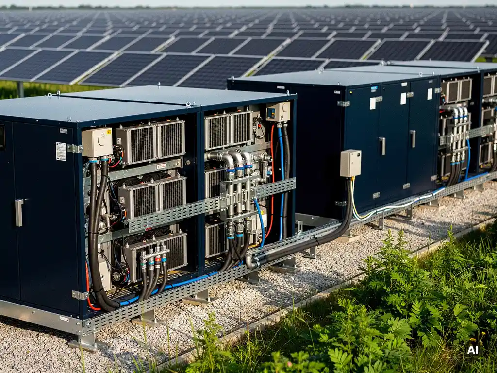

A battery storage system consists of five core components: the battery cells or modules (which store energy), a battery management system (BMS), a power conversion system (inverter or bidirectional converter), a thermal management system, and a control and monitoring interface. Together, these components determine how much energy the system can store, how safely it operates, and how efficiently it delivers power when needed.
Understanding each component matters because the performance of the whole system depends on how well these parts work together. For solar professionals designing PV systems with storage integration, getting this right from the engineering stage prevents costly rework later. The sections below break down how each component functions, what decisions they drive, and how they affect overall system design.
How does a battery storage system actually work?
A battery storage system works by converting electrical energy into chemical energy during charging, storing it within electrochemical cells, and then reversing that process during discharge to release electricity back into a circuit. In a solar context, excess PV generation charges the battery bank, and that stored energy is dispatched when generation drops or demand rises.
The process begins at the battery cells themselves, where electrochemical reactions move ions between electrodes through an electrolyte. During charging, an external current drives ions from the cathode to the anode. During discharge, the reaction reverses and electrons flow through the external circuit, producing usable current.
In a solar-plus-storage system, a power conversion system manages the interface between the DC output of the PV array, the DC battery bank, and the AC grid or load. Depending on whether the system is AC-coupled or DC-coupled, the conversion path differs, but the fundamental principle remains the same: store energy when it is cheap or abundant, release it when it is needed or valuable.
Control logic, typically embedded in an energy management system (EMS), governs when the battery charges and discharges based on grid signals, tariff structures, load forecasts, or self-consumption targets. This layer is what transforms a passive storage device into an intelligent grid asset.
What are the main components of a battery storage system?
The main components of a battery storage system are the battery cells or modules, the battery management system (BMS), the power conversion system (PCS), the thermal management system, and the energy management system (EMS) or control interface. Each component plays a distinct role, and the overall system performance is only as strong as the weakest link among them.
Battery cells and modules
The battery cells are the fundamental energy storage units. Individual cells are grouped into modules, and modules are assembled into racks or cabinets to reach the required energy and power capacity. Cell chemistry, form factor (cylindrical, prismatic, or pouch), and quality all directly affect energy density, cycle life, and cost.
Power conversion system
The power conversion system handles the transformation between DC power stored in the battery and AC power used by the grid or loads. In most utility-scale and commercial systems, this is a bidirectional inverter. The PCS must be sized to match both the peak power output required and the charging rate the battery can safely accept. Undersizing the PCS creates a bottleneck; oversizing it adds unnecessary cost.
Energy management system
The EMS is the intelligence layer that coordinates charging and discharging decisions. It receives inputs from grid meters, weather forecasts, load profiles, and market price signals, then dispatches the battery accordingly. In complex projects, the EMS also handles communication between multiple battery racks, inverters, and external SCADA systems.
What does a battery management system (BMS) do?
A battery management system (BMS) monitors and protects individual battery cells by tracking voltage, current, temperature, and state of charge in real time. It prevents cells from operating outside safe limits, balances charge across cells to extend pack life, and communicates critical data to the broader control system. Without a BMS, lithium-based batteries in particular would degrade rapidly or become a safety hazard.
The BMS performs cell balancing, which is the process of equalizing the state of charge across all cells in a module. Because no two cells are perfectly identical, some charge faster or hold more energy than others. Without balancing, the weakest cell limits the entire pack. Active balancing redistributes energy between cells; passive balancing dissipates excess energy as heat from the stronger cells.
Beyond protection and balancing, the BMS calculates state of charge (SoC) and state of health (SoH) estimates. SoC tells the system how much energy is currently available, while SoH tracks long-term capacity degradation. These values feed directly into the EMS dispatch logic, so inaccurate BMS readings lead to poor operational decisions and accelerated degradation.
For engineers integrating battery storage into PV designs, the BMS communication protocol matters. Most modern systems use CAN bus or Modbus TCP to relay BMS data to inverters and EMS platforms. Confirming protocol compatibility early in the design phase avoids integration headaches during commissioning.
What is the difference between AC-coupled and DC-coupled battery storage?
The key difference between AC-coupled and DC-coupled battery storage is where in the electrical circuit the battery connects. In an AC-coupled system, the battery has its own dedicated inverter and connects on the AC side of the PV inverter. In a DC-coupled system, the battery connects on the DC side, sharing the same inverter as the PV array or using a DC-DC converter before a shared inverter.
AC-coupled systems
AC-coupled storage is easier to retrofit onto existing PV installations because the battery system operates independently of the solar inverter. Each component has its own inverter, which adds flexibility but also introduces additional conversion losses. Every time energy moves from PV to battery and back to AC, it passes through two conversion stages, each with efficiency losses typically in the range of two to five percent per stage.
AC coupling is also preferred when the battery and PV systems are physically separated or when the project uses a string inverter topology where adding DC-side storage would be impractical.
DC-coupled systems
DC-coupled storage connects the battery directly to the DC bus, before the main inverter. This reduces conversion losses because solar energy can flow directly into the battery without first being converted to AC. DC coupling is generally more efficient for new-build systems and is well-suited to utility-scale projects where the inverter is sized to handle both PV and battery power flows.
The trade-off is complexity. DC-coupled systems require careful sizing of the shared inverter and DC-DC charge controller, and retrofitting them onto existing AC systems is rarely straightforward. For greenfield solar-plus-storage projects, however, DC coupling often delivers better round-trip efficiency and a simpler overall architecture.
Which battery chemistry is best for solar storage systems?
Lithium iron phosphate (LFP) is currently the most widely used battery chemistry for solar storage systems, and for good reason. LFP offers a strong balance of cycle life, thermal stability, safety, and cost. It tolerates partial states of charge well, which suits the variable charging patterns typical of solar applications, and it does not carry the thermal runaway risk associated with other lithium chemistries.
Nickel manganese cobalt (NMC) chemistry offers higher energy density than LFP, meaning more energy can be packed into a smaller physical footprint. This makes NMC attractive for space-constrained commercial rooftop applications. However, NMC cells are more sensitive to high temperatures and require more sophisticated thermal management to operate safely over their rated cycle life.
Lead-acid batteries, including advanced lead-carbon variants, remain in use for smaller off-grid and backup applications due to their low upfront cost and established supply chains. However, their lower cycle life, heavier weight, and sensitivity to deep discharge make them a poor fit for daily-cycling solar storage at commercial or utility scale.
Flow batteries, particularly vanadium redox flow systems, are gaining traction for long-duration storage applications where four or more hours of discharge capacity is required. Their key advantage is that energy capacity and power capacity are independently scalable, and they do not degrade in the same way as solid-state chemistries. The trade-off is higher capital cost and a larger physical footprint per kilowatt-hour.
For most commercial and utility-scale solar projects in 2026, LFP remains the default choice, with NMC considered where space is the binding constraint and flow batteries evaluated only when long-duration storage is a specific project requirement.
How does thermal management affect battery storage performance?
Thermal management directly affects battery storage performance, safety, and lifespan. Lithium-based batteries operate most efficiently within a defined temperature window, typically between 15°C and 35°C. Operating consistently outside this range accelerates capacity degradation, reduces round-trip efficiency, and in extreme cases creates safety risks, including thermal runaway.
High temperatures are the primary enemy of battery longevity. Elevated cell temperatures accelerate the chemical reactions that cause capacity fade, meaning a battery cycled in a hot climate without adequate cooling will reach end-of-life significantly earlier than its rated cycle count suggests. This has direct implications for project economics, since battery replacement is one of the largest lifecycle costs in a storage system.
Cold temperatures present a different problem. At low temperatures, internal resistance increases and the battery cannot deliver or accept charge at its rated rate without risking lithium plating on the anode, which permanently reduces capacity. Systems deployed in cold climates often require active heating to bring cells up to operating temperature before charging begins, adding both energy consumption and system complexity.
Thermal management systems use one of three approaches: passive cooling (relying on natural convection and the thermal mass of the enclosure), active air cooling (fans circulating air through the battery cabinet), or liquid cooling (circulating a coolant fluid through channels in direct contact with the cells or modules). Liquid cooling is more effective and more precise, but adds cost and maintenance requirements. For high-cycle commercial and utility applications, liquid cooling is increasingly standard because the improvement in cycle life typically justifies the additional investment.
Engineers designing solar-plus-storage systems should account for thermal management load in their energy balance calculations. Active cooling and heating systems consume parasitic power that reduces the net round-trip efficiency of the storage system, and this should be reflected in yield simulations and financial models.
If you are working on a solar project that includes battery storage integration and want to streamline the engineering workflow, Virto Solar offers tools built specifically for PV professionals who need accurate, construction-ready designs without the manual overhead. For project-specific questions, you can also get in touch with our team directly.
Frequently Asked Questions
How do I determine the right battery storage capacity for a solar project?
Start by analyzing the site's load profile and identifying when generation and consumption are misaligned — that gap defines the minimum useful storage capacity. From there, factor in the desired autonomy duration, the depth of discharge the chosen chemistry supports, and any grid export limits that may apply. For commercial and utility-scale projects, running an energy simulation that models hourly PV generation against load demand will give you a much more accurate capacity target than rule-of-thumb sizing.
What is round-trip efficiency and why does it matter for project economics?
Round-trip efficiency (RTE) is the ratio of energy retrieved from a battery to the energy that was put into it, expressed as a percentage. A system with 90% RTE loses 10% of every kilowatt-hour cycled through it, and those losses compound over thousands of cycles across the project lifetime. When building financial models, understating these losses — or ignoring parasitic loads from thermal management — leads to overstated revenue projections and can make a marginal project look viable on paper when it isn't.
What are the most common mistakes engineers make when integrating battery storage into a PV system design?
The most frequent mistakes are mismatching the power conversion system capacity to the battery's charge/discharge rate, overlooking BMS communication protocol compatibility with the inverter and EMS, and failing to account for thermal management parasitic loads in the energy balance. Another common oversight is not verifying that the battery's DC voltage window aligns with the inverter's operating range, which can cause the system to derate or shut down under real operating conditions.
Can an existing solar installation be retrofitted with battery storage, and what should I check first?
Yes, most existing PV systems can be retrofitted using an AC-coupled configuration, since the battery system connects independently on the AC side without requiring changes to the existing solar inverter. Before specifying a retrofit, verify the existing inverter's export limiting and communication capabilities, confirm the switchboard has sufficient capacity for the additional load, and check whether the grid connection agreement permits storage. In some jurisdictions, adding storage triggers a new grid application, so confirming regulatory requirements early avoids project delays.
How does depth of discharge affect battery lifespan, and what is a realistic operating range?
Depth of discharge (DoD) refers to how much of the battery's total capacity is used in each cycle — a higher DoD means more stress on the cells and a shorter cycle life. Most LFP systems are rated at 80–90% DoD, but operating consistently at the upper limit will degrade the pack faster than the headline cycle count implies. In practice, many commercial system operators set a working DoD of 80–85% to extend calendar life, which should be reflected in both the dispatch strategy and the degradation assumptions in your financial model.
What safety standards and certifications should a battery storage system meet for commercial or utility-scale projects?
At a minimum, look for compliance with IEC 62619 (safety requirements for lithium cells and batteries in stationary applications) and UL 9540 (standard for energy storage systems), with UL 9540A test data available if the project requires fire safety analysis for permitting. The battery enclosure should also meet relevant IP and IK ratings for the installation environment. For grid-connected systems, confirm that the PCS holds the appropriate grid connection certification for your market — in Europe this typically means compliance with EN 50549 or the relevant national grid code.
How should battery storage degradation be modeled over a project's lifetime?
Battery degradation is driven by both cycle aging (capacity loss per charge-discharge cycle) and calendar aging (capacity loss over time regardless of use), and a realistic model needs to account for both. Manufacturers typically provide cycle life curves at a specified DoD and temperature — apply a derating factor if your operating conditions differ from those test conditions. A common approach for 20-year project models is to assume 20–30% capacity loss by end of life for LFP under daily cycling, with a battery augmentation or replacement event scheduled mid-life if the capacity floor triggers contractual or performance obligations.
Related Articles
- What is included in a construction-ready solar wiring diagram?
- What is battery storage for solar energy?
- How many kWh of battery storage do I need?
- What tools automate BESS engineering calculations?
- How do you size a battery for peak shaving?
This content was generated with the help of AI — it may contain mistakes