How to Design a Shading Free Solar System Layout
")
When you’re about to start planning and designing a new large-scale solar project, it is important to take shading and energy losses into account. The goal of large-scale solar plants is to generate as much energy as possible. All the energy that has been generated will be converted into power that can be used by families, companies or solar car parks, for example. For this reason, it is crucial to limit shading on your solar system to an absolute minimum or if possible, even avoid any shading at all. We can achieve this by designing the most optimal solar system layout as possible.
Shading Explained
Solar modules generate energy by absorbing sunlight during daytime hours, either directly or indirectly.
Direct sunlight means that the sun rays hit the solar modules in “one direct way”. This type of sunlight generates the most energy.
Indirect sunlight results in a slower energy generation since the sun rays are hitting the solar modules in a different way. For instance, this happens when sun rays need to travel through clouds on a cloudy day. Solar modules are still working and generating energy but at a much slower rate.
Shading can be the result of many causes, for instance:
- Physical objects and obstacles
- Trees, buildings, chimneys, etc.
- Other solar modules or solar racks, mounting structures, etc.
- Weather conditions
- Rain, clouds, snow, etc.
- Geographical conditions
- Mountain or hill sides, the terrain, location on earth (longitude and latitude), …
- Other causes such as dirt, dust, … etc.
How to Avoid Shading in a Solar System Layout
As we’ve explained earlier, it is important to avoid shading in your solar system layout as much as possible in order to achieve maximal solar yield. There are a few things to consider in the design process.
Know your solar modules: classic or half-cut cells*
The type of solar module has an impact on your solar photovoltaic layout. Classic solar modules are much more affected by shading than solar modules with half-cut solar cells, for instance. Half-cut solar cells have many advantages:
- Better performance
- Longer lifespan
- Physically more resilient, smaller and less prone to breaking
- Higher output numbers
- They minimize the damage while reducing the hotspots
- Cut down on resistive losses
- Shade tolerance is higher
Bypass diodes & Half-cut cells*
Bypass diodes are small devices that are built into the PV solar module itself and allow the current to “skip over” some solar cells that are being shaded.
By using bypass diodes, the current of the shading free solar cells is not being reduced by the lower current of the shaded cells. On the one hand this is a good thing: the current remains higher. However, the solar output of the shaded solar cells is completely lost.
Ideally all solar cells have a bypass diode, however, this is very expensive. Therefore, often a 60-module is built of 3 strings and each solar cell circuit contains one bypass diode for 20 solar cells. If there’s shade on 1 solar cell circuit, one loses a third of this solar modules’ solar output.
In order to improve the performance of solar modules, one can also use “half-cut cell solar modules” containing 120 cells and 6 solar cell circuits. If there’s shade on one solar cell circuit, only a sixth of the solar output is lost.
Knowing the difference between the more classic 60-cells modules and the half-cut cells modules, helps us optimizing the solar system layout. For instance, we now know that there’s only 3 solar cell circuits in a classic solar module. These circuits run over the entire module. If there’s shade on one part, we’ll lose the entire solar output. Therefore, when using classic solar modules, it’s better to use a landscape solar layout when there’s shadow involved.


Rooftop Versus Ground-Mounted Solar System Layout
Shading occurs differently for photovoltaic rooftop systems and utility-scale ground-mount systems. We’ll go deeper into differences and how to avoid energy loss to due shading during the solar engineering process below.
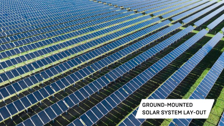
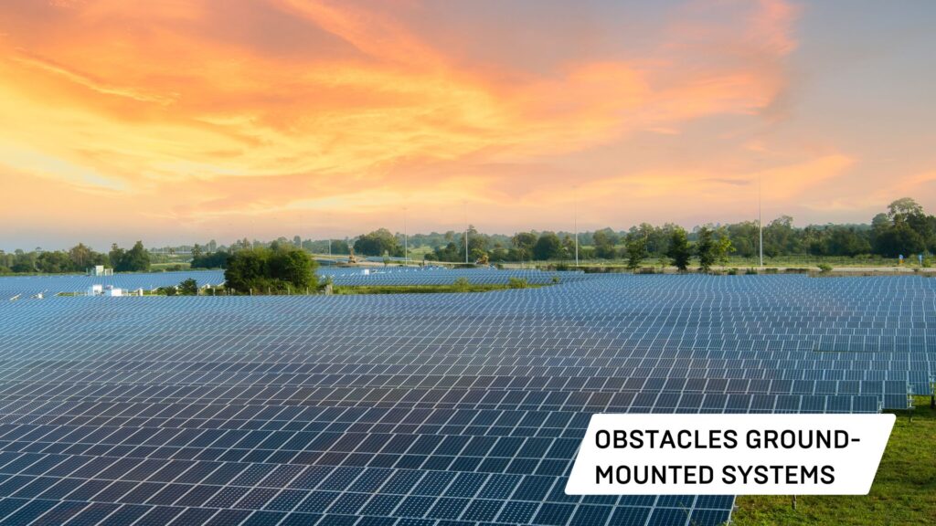
Ground-mounted systems
On the one hand, there is a risk of shading on ground-mounted solar systems due to other objects and obstacles that are in the surrounding area of the solar modules.
For instance: trees in or around fields can cause shadings at certain moments in the day – or even all day. Therefore, it is important to map and recognize other objects and obstacles in order to adjust or remove certain photovoltaic solar modules which may not generate sufficient energy yield.

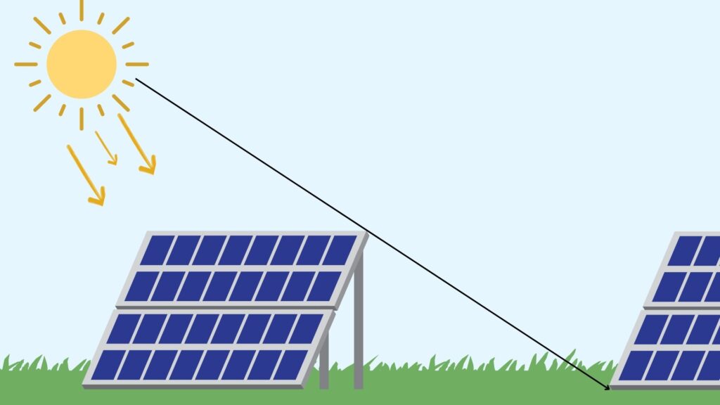
On the other hand, shadings can also occur if solar racks and solar mounting structures are not placed in the best position. For instance, if solar racks are placed to close to each other, it is possible they will cause shadings on the surrounding solar modules during daytime. As we’ve explained earlier, one also has to decide on placing the solar modules in either a landscape or portrait layout to avoid as much shading as possible.
Lastly, the terrain also has an impact on what the best lay-out is for your solar modules and solar racks. For instance, hill- or mountainsides can also influence how shading falls on surrounding solar modules.
PV design software allows you to build on Google Maps visuals or to upload your own visual materials to map and recognize objects and obstacles.
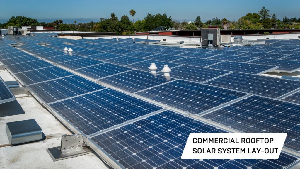
Rooftop Systems
The most common cause of energy loss due to shadings with rooftop solar systems, are obstacles and objects on or around the rooftop. Surrounding buildings, trees, a chimney, air conditioning units, … are just a few examples.
Unlike ground-mounted solar systems, it is rare that other solar modules or mounting structures will cause shading in commercial rooftop layouts.
It’s crucial to know that if one solar modules is being affected by shading, this will affect the entire energy flow. Photovoltaic rooftop systems are based on “strings”. In many cases about 20 to 30 solar modules are connected to each other by means of one string.
If there’s shading on one part of a solar module, this will affect the solar output of the entire module. This is because all other solar cells will “follow the lowest solar cell’s current”. A shaded solar cell generates less power resulting in all other solar cells generating only the same amount of power. As a result, this solar pa module will not operate at maximum power.
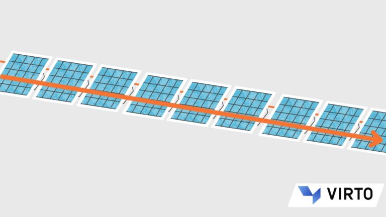
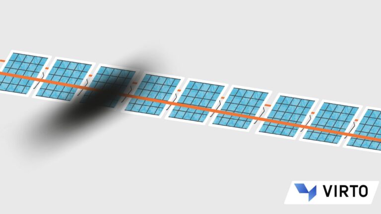
The same thing applies to solar modules that are connected to each other by a string. When there’s shade on one solar module, all others will be affected too: the shaded module generates less power and all other modules in the same string will generate only the same reduced amount of power. So even the solar modules that are not affected by any shade, will not work and generate at maximum power.
How Virto.CAD Helps You Optimize Your Solar System Layout
Virto.CAD PV design software offers a wide range of tools and solutions that can be used by engineers to design, engineer and optimize large-scale solar park projects. Our PV CAD plugin has been built in such a way that it offers so many advantages : it automates the entire engineering process. Calculations, layouts, 3D modelling, … are generated automatically and require no manual input. As a result, your engineering process will be fast, efficient and most importantly, accurate. Below we will go a little deeper into all the cutting-edge Virto.CAD has to offer for both ground-mounted PV solar layouts and commercial rooftop projects.
Optimize Ground-Mounted Solar Projects
As we’ve highlighted earlier, on of the most common causes for energy loss due to shading are obstacles, objects on the one hand; on the other hand, also the solar racks and solar modules itself.
You can choose to either work with Google Maps visuals or upload your own visual material such as .png and .pdf. In addition, we’re partnering with Plex-Earth which allows you to easily work with complete 3D geographical imagery of your projects area. Virto.CAD will then use these visuals as an underlay for you to start designing your solar park on top.
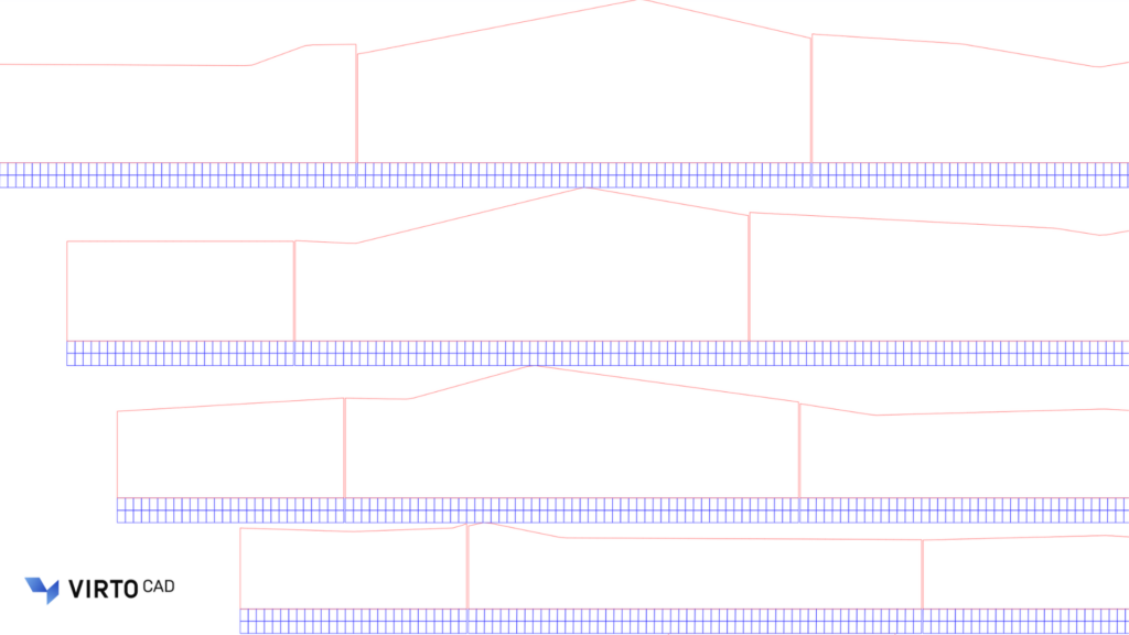
After selecting the terrain and project area, you can upload weather data and set parameters in order to calculate irradiance. Irradiance is calculated based on ray tracing. Virto.CAD uses colours to show the amount of irradiance – where purple stands for a lot of shading ranging to red – meaning there’re no shading levels being detected. Based on this you can decide to adjust your solar system layout or remove any modules to optimize your energy yield. Our PV software allows you to integrate PVsyst – a highly qualitive tool to calculate solar energy yield.
Furthermore, Virto.CAD takes the “shading angle” into account while calculating the lay-out of your solar park. The “shading angle” is used to indicate the starting point of your new line of solar racks and solar modules. Our PV software avoids putting solar racks to close to each other and generates the result automatically and in 3D vision.
Optimize Rooftop Solar Projects
Shadow & Irradiation simulation
When you start the design and engineering process of commercial rooftop solar systems, it’s essential to map the environment and location. You start off by uploading your own imagery or use Google Maps or Plex-earth to set up your underlay.
Virto.CAD maps and recognizes rooftop objects and obstacles and lets you add new items yourself. For instance, there may be differences in rooftop levels in which case a higher rooftop level creates shading on the lower rooftop level. In this case you want to map the shading areas.
PV design software allows you to simulate these shadow areas and the irradiation of the sun based on weather data. You can easily simulate and calculate the irradiance on either your roof surface or on the modules.
By setting a “threshold” parameter, our PV software will show the results with the use of colours. Then you can choose to either remove solar modules or not, based on the generated data.

Stringing Arrangements
We have also implemented a tool to optimize the PV layout of your solar modules and its stringing arrangements in Virto.CAD.
Photovoltaic modules are connected by strings; these strings are then connected in parallel to an inverter. The current that flows through all solar modules is the same. More importantly, the current is easily impacted by one solar module. One module can cause the entire string to generate significantly less power.
We can solve this issue by grouping all nearby solar modules that will or may have some shading into one string. A shaded PV module in one string does not affect any other PV modules in a parallel string. So, by grouping all shaded modules into separate strings, we can optimize the PV module layout and power output of the entire array of PV modules.
To sum up
The goal of large-scale solar parks is to generate as much energy as possible. Therefore, it is crucial to plan, design and engineer these solar parks in such a way to ensure an optimal solar system layout.
With the use of Virto.CAD PV design software, you can engineer your utility-scale ground-mounted projects and commercial rooftop systems shading free or as shading free as possible.
Our partner plugins “Plex-Earth” and “PVsyst” offer you additional features to facilitate the engineering process.
Do you want to see how our photovoltaic design software works or are you excited to get started right away? Request a free trial or schedule a free demonstration. Our team will be more than happy to assist you or answer any questions you have.
Virto.CAD is compatible with AutoCAD or BricsCAD (BIM).
Get In Touch
Request a free trial, schedule a demo, give us your feedback or ask us anything!
Simply drop us an email or give us a call.
Our team will be happy to assist you.